")
")

The ATmega328P microcontroller (MCU) contains three input/output ports: PORTB, PORTC, and PORTD. Ports can be understood as groups of pins accessible from the outside of the MCU. Each port has 8 bits (8 pins). Each pin can be set as input or output, or it can perform a specific function such as a UART communication pin. The equivalent circuit diagram of a pin is shown in the image below. Each pin contains protective diodes and an adjustable pull-up resistor.
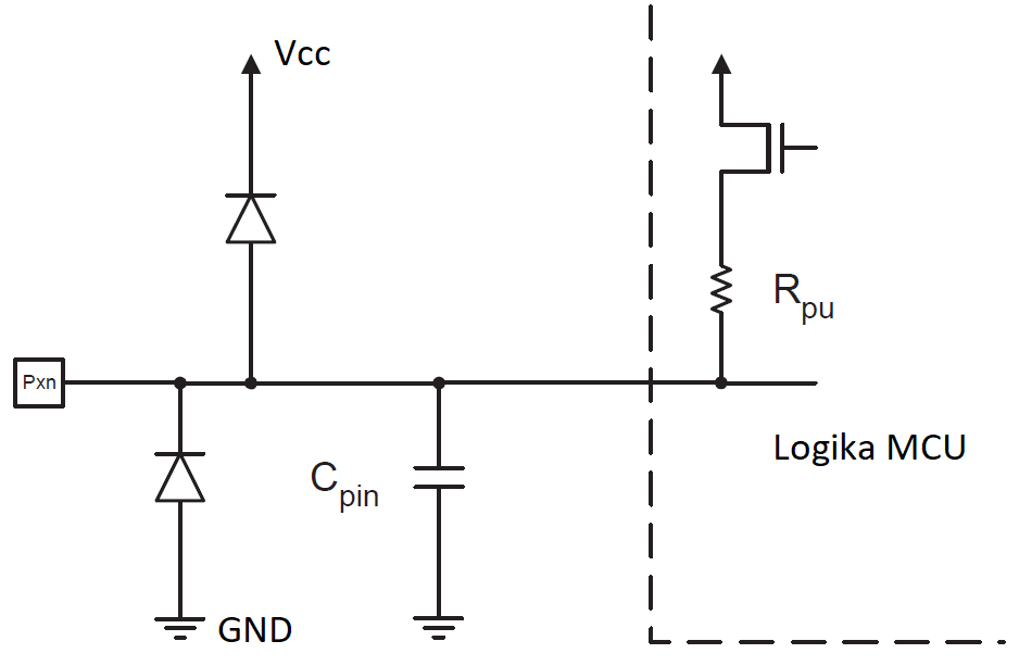 Equivalent circuit of an I/O pin.
To work with the input/output ports, three registers are used: PORTx (Data Register), DDRx (Data Direction Register), and PINx (Port Input Pins), where x represents the letter of the port, i.e., B, C, or D. The PORTx and DDRx registers allow reading and writing individual bits, while the PINx register is for reading only. Writing to the PINx register changes the value of the corresponding bit in the PORTx data register.
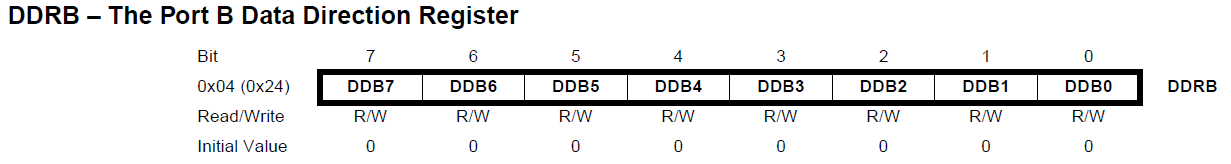
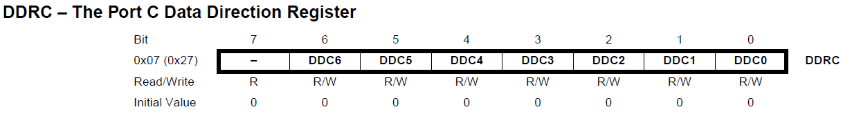
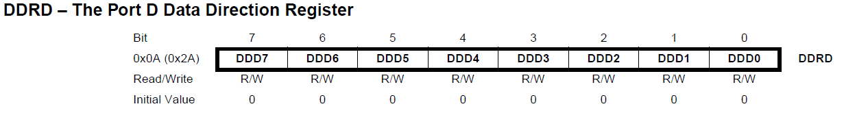
The DDRx register is used to set the "direction" of a given pin, i.e., whether the pin is input or output. The individual bits of this register are labeled as DDxn, where n is the ordinal number of the given bit in the DDRx register. If the DDxn bit value is set to logical one, the corresponding n pin will be configured as output. Conversely, if the bit value is set to logical zero, the n pin is configured as input.
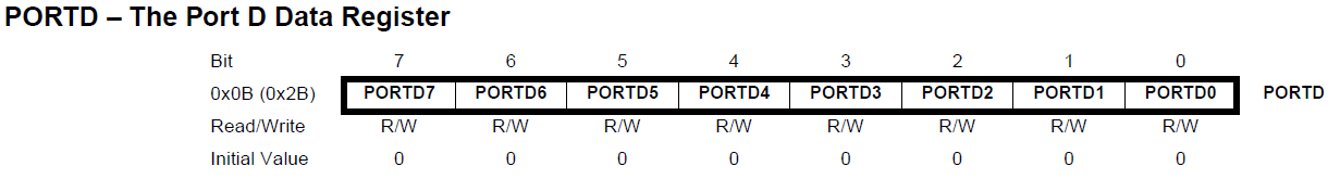
When writing to the PORTx register, two different situations can occur depending on the state of the corresponding DDRx register:
- If the port pin is set as output (DDxn=logical 1), then writing a logical one to the corresponding bit of the data register (PORTxn=logical 1) sets a logical one (high voltage level) on the corresponding pin. Writing a logical zero (PORTxn=logical 0) sets a logical zero (low voltage level) on the pin.
- If the port pin is set as input (DDxn=logical 0), then writing a logical one to the corresponding bit of the data register (PORTxn=logical 1) activates the pull-up resistor on the pin. If the data register bit is set to logical zero (PORTxn=logical 0), the pull-up resistor on the pin is disconnected.
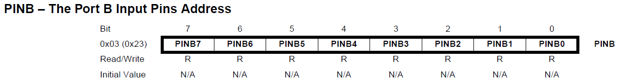
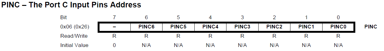
The state of the pin can be determined by reading the bit of the PINxn input register, regardless of the DDxn bit setting in the DDRx register. Writing a logical one to the PINxn bit changes the value of the PORTxn bit regardless of the DDxn bit state.
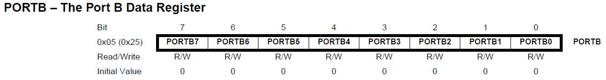
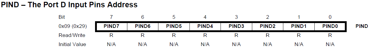
Below are all the registers used for pin configuration. In the description of the registers, the first row shows the ordinal bit number. The row below shows the name of the bit (the framed part). The next row shows whether the bit is for writing (W), reading (R), or both reading and writing (R/W). The last row shows the preset value of the bit (after reset or connecting the microcontroller to power). Usually, this value is zero, but it can also be one, so always check this value in the datasheet! If you have no experience setting or reading bit values in registers, go to working with registers to learn more.
PORTB, DDRB, PINB - Registers used for configuring the input/output pins of port B.
PORTC, DDRC, PINC - Registers used for configuring the input/output pins of port C.
Note! Port C has only 7 pins!

PORTD, DDRD, PIND - Registers used for configuring the input/output pins of port D.
#define F_CPU 8000000UL //definícia frekvencie MCU, nutné pre knižnicu delay.h
#include <avr/io.h>
#include <util/delay.h>//knižnica pre _delay_ms()
int main(void)
{
DDRB=255;//dekadický zápis, všetky vývody portu B ako výstupné
while (1)
{
PORTB|=(1<<PORTB0);//zasvietenie LED0
_delay_ms(500);//pauza 500ms
PORTB&=~(1<<PORTB0);//zhasnutie LED0
_delay_ms(500);//pauza 500ms
}
}
#define F_CPU 8000000UL //definícia frekvencie MCU, nutné pre knižnicu delay.h
#include <avr/io.h>
#include <util/delay.h>//knižnica pre _delay_ms()
int main(void)
{
DDRB=255;//všetky vývody portu B ako výstupné - LEDky
DDRD=0;//všetky vývody portu D ako vstupné - tlačidlá
PORTD=255;//zapnutie pull-up rezistorov na celom porte D, nestlačené tlačidlo má log. 1
uint8_t blikLED=0;//ak blikLED=0 -> bliká LED0; ak blikLED=1 -> bliká LED1
while (1)
{
//zistím, či bolo stlačené S7
if (PIND&(1<<PIND7)==0)//stlačením tlačidla privediem log. 0 na PIND7
{
blikLED=0;//bude blikať LED0
}
//zistím, či bolo stlačené S6
if (PIND&(1<<PIND6)==0)//stlačením tlačidla privediem log. 0 na >PIND6
{
blikLED=1;//bude blikať LED1
}
if (blikLED==0)
{
PORTB|=(1<<PORTB0);//zasvietenie LED0
_delay_ms(500);//pauza 500ms
PORTB&=~(1<<PORTB0);//zhasnutie LED0
_delay_ms(500);//pauza 500ms
}
else
{
PORTB|=(1<<PORTB1);//zasvietenie LED1
_delay_ms(500);//pauza 500ms
PORTB&=~(1<<PORTB1);//zhasnutie LED1
_delay_ms(500);//pauza 500ms
}
}
}