")
")
AVR microcontrollers from Atmel are very popular in our region and are used by many beginners as well as experienced MCU programmers. They are 8-bit microcontrollers with high performance, relatively low power consumption, and a large number of peripherals. This article describes the design and construction of a development board for the ATmega328p microcontroller, which is easily available at an affordable price. The board is ideal for beginners who are starting to learn how to program microcontrollers.
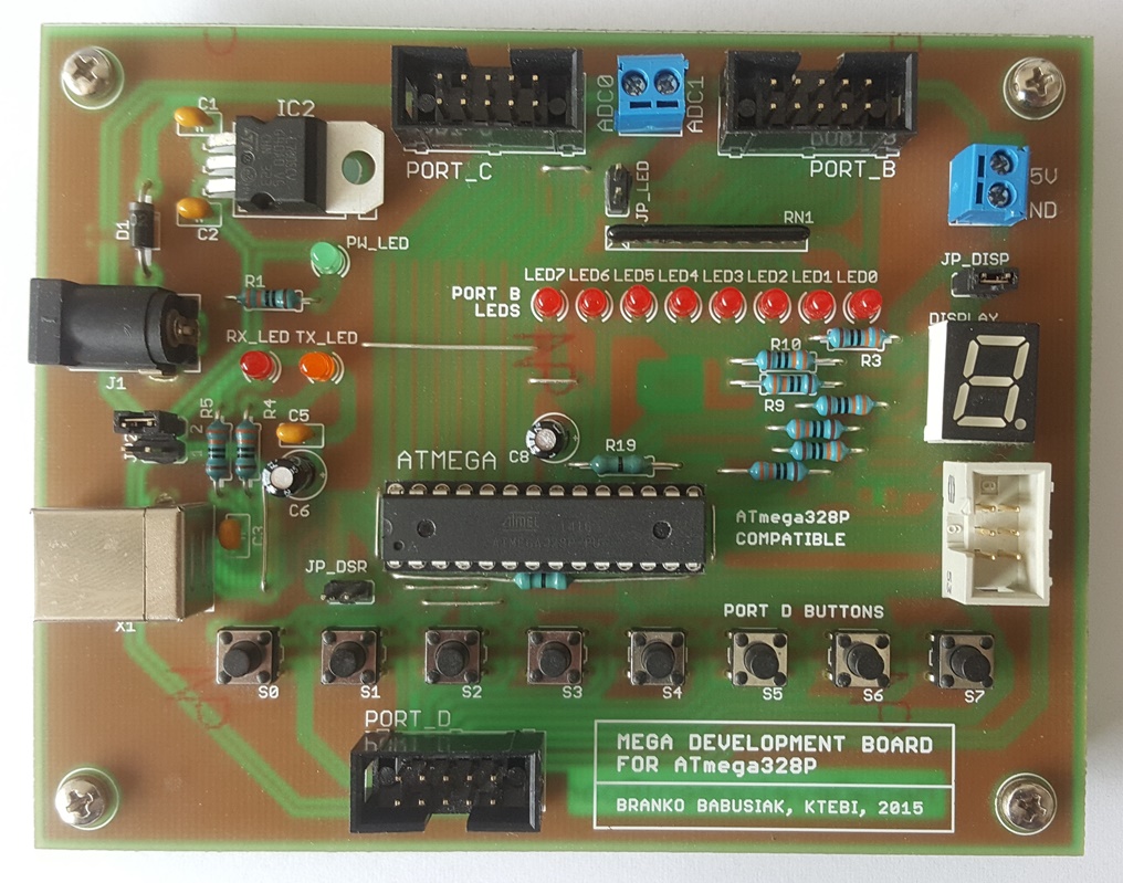 Fig. 1: Development board for ATmega328p.
The development board is primarily designed for the ATmega328p microcontroller with a DIP package. The board can also be used for other types of MCUs that have the same pinout, such as ATmega48A/PA/88A/PA/168A/PA. This board was not originally designed for these types, and therefore some of its functions may not be compatible with the peripherals of these microcontrollers, so the connection needs to be verified in the datasheets.
Circuit Description
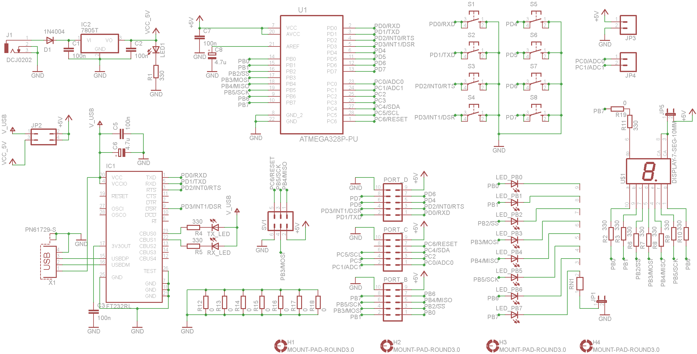 Fig. 2: Circuit diagram of the development board for ATmega328p.
The development board is powered by a 5V DC voltage, which is regulated by the 7805 (IC2) stabilizer. Diode D1 provides protection against reverse polarity of the power source. The board is powered by a DC adapter with a voltage of up to 35V depending on the type of 7805 stabilizer. I recommend using a 12V adapter to prevent excessive heating of the stabilizer. The adapter connection is indicated by LED1. Alternatively, the board can be powered from a PC USB port by connecting the board to the PC with a suitable USB cable. For this case, it is necessary to move the jumper on the pin header JP2. This method of power supply is less suitable for beginners because accidental short circuits can disconnect the USB port in the PC and, in the worst case, it can be damaged.
The ATmega328p contains 3 input-output ports, which are brought out using 10-pin connectors (PORT_B, PORT_C, PORT_D) on the PCB. Port D is connected to 8 buttons (S1 - S8), which can be used to set the inputs for the MCU. When a button is pressed, a logical zero value is brought to the corresponding MCU input. Pull-up resistors are not used for the buttons because the MCU inputs can be programmed to enable pull-up resistors. Port B is connected to LEDs (LED_PB0 – LED_PB7) and an 8-segment display with a common anode. If we only want to use the display, we can deactivate the LEDs by removing the jumper JP1. If we want to deactivate the display, we remove the jumper JP5. An LED is lit by bringing a logical one to the corresponding port B output. Conversely, a display segment is lit by bringing a logical zero to the corresponding port B output. The board also contains a JP3 terminal block for bringing +5V power and ground to peripheral circuits and a JP4 terminal block for bringing an analog signal to the two inputs of the AD converter ADC0 and ADC1. The AD converter has a 10-bit resolution and can digitize voltages in the range of 0 to +5V. Exceeding this range can irreversibly damage the AD converter as well as the entire MCU. The ATmega328p in the PDIP package has a total of 6 AD converter channels that can be used by connecting to the PORT_C connector, even though only the first two channels are brought out on the PCB using the JP4 terminal block. It is also possible to use all available MCU peripherals such as counters, timers, communication interfaces – UART, I2C, and SPI through the connectors PORT_B, PORT_C, and PORT_D. The UART communication interface is very popular and widely used. Since new PCs usually lack a serial port, the UART interface is converted to a USB interface using the FT232RL interface converter. The board is connected to the PC using a standard USB cable with USB-A and USB-B ends. A virtual serial port is created in the PC upon connection, which can be used as a classic UART interface. Data reception and transmission are indicated on the PCB by the RX_LED and TX_LED LEDs.
MCU Programming
The microcontroller supports ISP (In-System Programming), meaning that the MCU can be programmed directly in the designed circuit without the need to program the MCU separately. Programming is done via a 6-pin ISP connector SV1, which uses the SPI interface. I personally use the AVR Dragon from Atmel for programming, which allows debugging the program directly on the chip. I recommend not soldering the MCU directly to the PCB, but using a DIL28 socket. The MCU can be inserted into this socket and removed for programming, or easily replaced in case of damage.
PCB Construction
The development board is made of a single-sided printed circuit board measuring 119 x 94 mm. Mostly classic leaded components are used. Surface mount components (SMD) could not be avoided because the FT232RL converter is only available in this version and represents the most challenging component to solder on the entire PCB due to its relatively small size. The PCB also contains 7 resistors and 1 capacitor in SMD version. The printed circuit board is shown in Fig. 3. The component side of the board is shown in Fig. 4 and the solder side in Fig. 5.
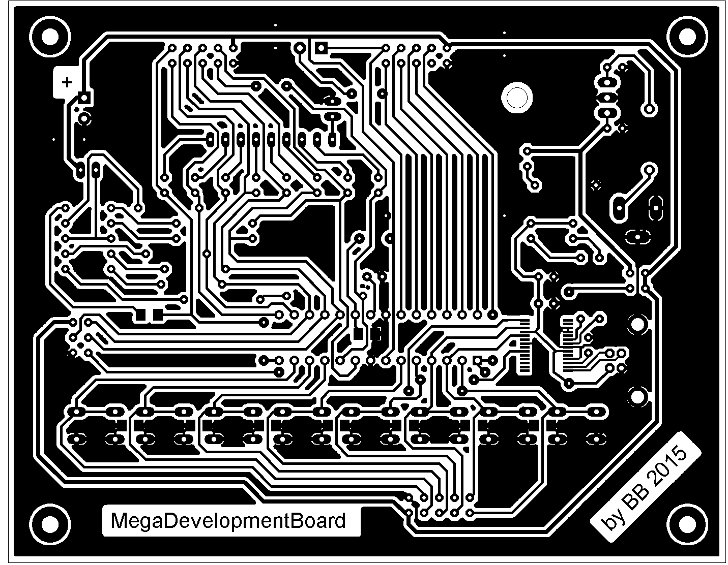 Fig. 3: Printed circuit board (119 x 94 mm).
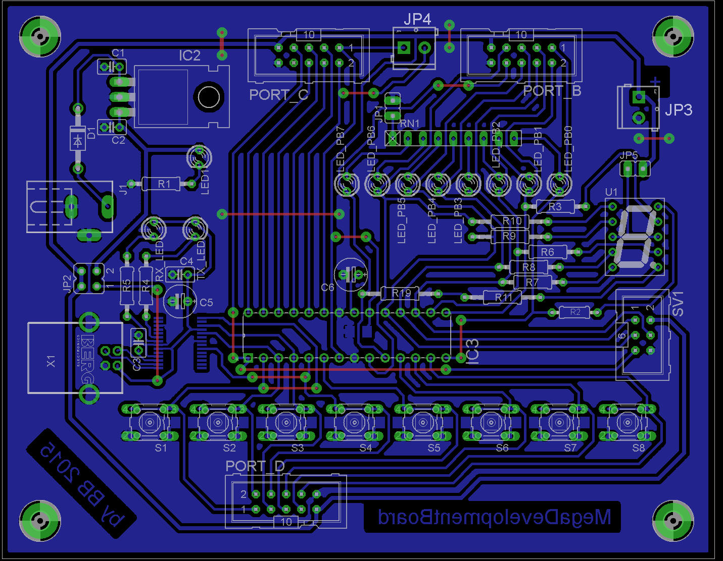 Fig. 4: Component layout (component side).
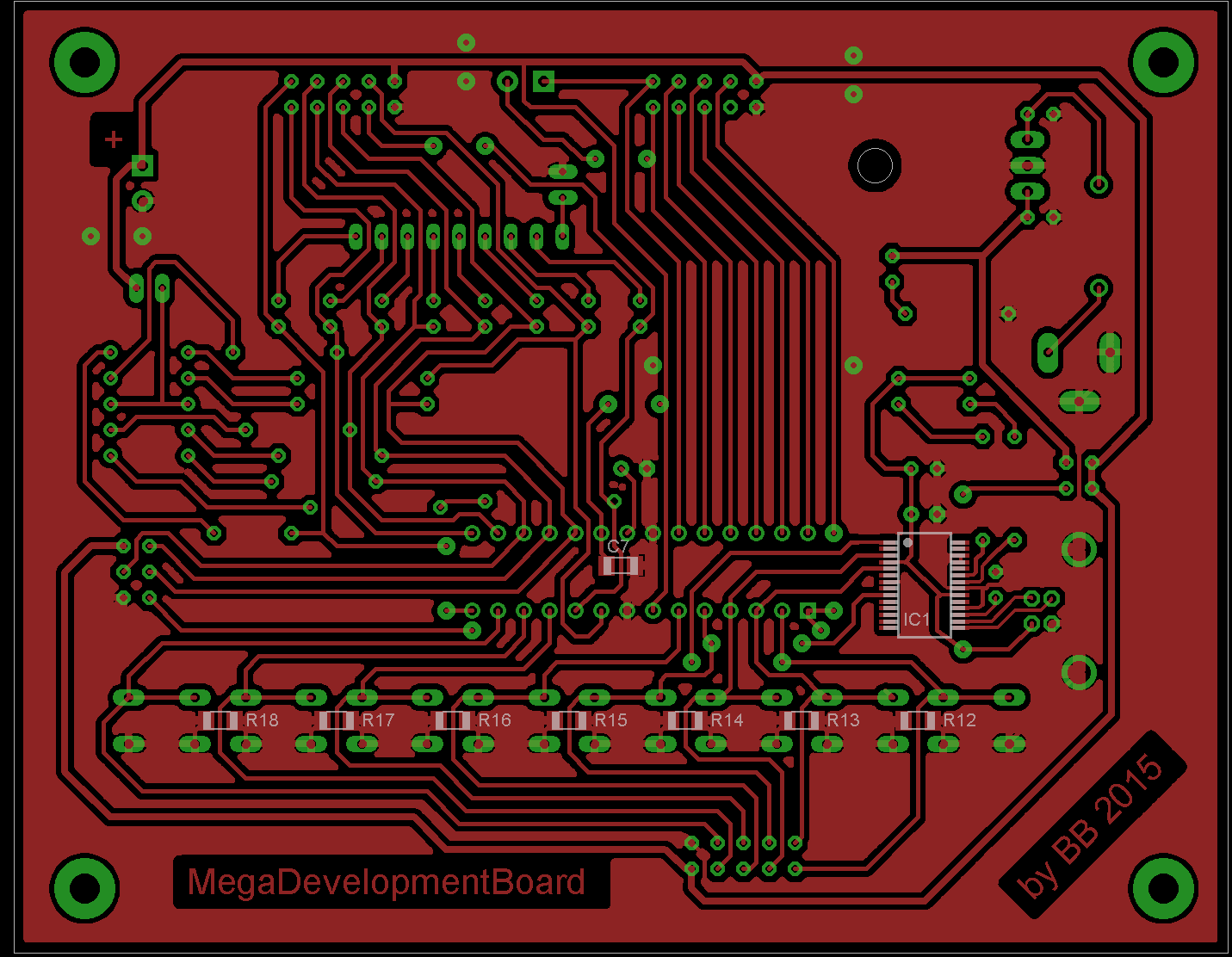 Fig. 5: Component layout (solder side).
Conclusion
The created development board for the ATmega328p is an excellent tool for developing new devices that include this popular microcontroller. With the exposed ports, it allows connecting any external circuits. The board has outputs for LEDs and a 7-segment display, and buttons are connected to the inputs, making it very useful for beginners who are starting with MCU programming.
List of Components Used
| R1-R11 | 330 Ω |
| R12-R18 | 0 Ω (SMD 1206) |
| R19 | 0 Ω |
| RN1 | resistor network 330 Ω (9-pin, 8 resistors) |
| C1-C4 | 100 nF |
| C5-C6 | 4.7 µF (electrolytic) |
| C7 | 100 nF (SMD 1206) |
| D1 | 1N4001-1N4007 |
| LED1 | 3mm green LED |
| RX_LED | 3 mm LED |
| TX_LED | 3 mm LED |
| LED_PB0 - LED_PB7 | 3 mm LED |
| IC1 | FT232RL |
| IC2 | 7805T |
| IC3 | socket for ATmega328p (PDIP28) |
| J1 | DCJ0202 (DC connector) |
| JP1, JP5 | jumper header 1x2 |
| JP2 | jumper header 2x2 |
| JP3, JP4 | 3.5 mm terminal block |
| PORT_B, PORT_C, PORT_D | ML10 (connector for flat cable) |
| SV1 | ML6 (connector for flat cable) |
| S1-S8 | button |
| U1 | 7-seg. display (common anode), 10 mm |
| X1 | USB-B connector |
Downloads
PCB Design in EAGLE