")
")
The nRF24L01+ module is a cheap wireless module operating at a frequency of 2.4 GHz. Its range is approximately 50 to 200 feet (15 - 61 m). The range mainly depends on the set power, data transfer rate, and interference from surrounding WiFi networks. It can be used for device control and sensor status monitoring within its range. The module is available in two basic designs: with a built-in antenna on the PCB and with an external antenna.
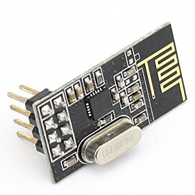 Version with antenna on PCB.
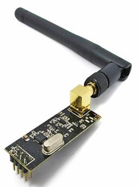 Version with external antenna.
The pin configuration of the module is shown in the following image and their meaning is given in the table.
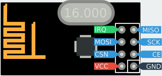 nRF24L01+ pin configuration.
| Pin | Name | Function | Description |
|---|---|---|---|
| 1 | GND | Power | Ground (0V) |
| 2 | VCC | Power | +1.9V – +3.6V |
| 3 | CE | Digital Input | Chip Enable (activates RX or TX mode) |
| 4 | CSN | Digital Input | SPI Chip Select |
| 5 | SCK | Digital Input | SPI Clock |
| 6 | MOSI | Digital Input | SPI Slave Data Input |
| 7 | MISO | Digital Output | SPI Slave Data Output |
| 8 | IRQ | Digital Output | Maskable interrupt pin. Active low. |
Connection with AVR (ATmega328P)
| nRF24L01+ | ATmega328P (name) | ATmega 328P (pin) |
|---|---|---|
| GND | GND | |
| VCC | VCC (3.3V) | |
| CE | Any I/O pin configured as output | PB6 |
| CSN | SS | PB2 |
| SCK | SCK | PB5 |
| MOSI | MOSI | PB3 |
| MISO | MISO | PB4 |
| IRQ | Any I/O pin configured as output | PB7 |
Programming AVR
The names of the nRF24L01+ registers and individual bits are in the header file nRF24L01.h. Mapping registers allows clear access and setting of individual registers. For example, to access the configuration register, we use the name STATUS instead of 0x07.
Communication via SPI
Mutual communication between the wireless module and AVR takes place via the SPI interface. The definition of individual pins and functions for the SPI interface looks as follows:
#define MOSI PORTB3
#define MISO PORTB4
#define SCK PORTB5
#define SS PORTB2
#define SPI_PORT PORTB
#define SS_enable() PORTB &= ~(1 << SS)
#define SS_disable() PORTB |= (1 << SS)
The SS_enable() function is used to select the chip for communication via the SPI interface. SS_enable() sets the SS output (PB2) to logic 0, because the output is inverted. Initialization of the SPI interface for ATmega328P looks as follows:
void SPI_Init(){
// Set MOSI, SCK, SS as Output
DDRB|=(1<<MOSI)|(1<<SCK)|(1<<SS);
// set MISO as Input
DDRB&=~(1<<MISO);
SPI_PORT|= (1<<SS) | (1<<MISO);
SPCR=(1 << SPE) | (1 << MSTR); //SPE - enable SPI, MSTR - MASTER mode
SPCR &= ~(1<< DORD);
//prenos zacina od MSB first
//nastavenie rychlosti prenosu SCLK pri Fosc=8 MHz -> 1 MHz (SPI2X=1)/500 kHz (SPI2X=0)
SPCR |= (1 << SPR0); //predelicka Fosc/8 - treba zapnut bit SPI2X v SPSR na double speed
SPSR |= (1<< SPI2X); //dvojansobna rychlost
SS_disable(); //aby nebol vybraty cip hned po inicializacii
}
To send one byte via SPI, we use the function:
void SPI_MasterTransmit(unsigned char cData){
/* Start transmission */
SPDR = cData;
/* Wait for transmission complete */
while (!( SPSR & (1<< SPIF)));
}
To send one byte via SPI with synchronous response (byte) from the slave device, we use the function:
unsigned char SPI_MasterTransmitSync(unsigned char cData)
{
/* Start transmission */
SPDR = cData;
/* Wait for transmission complete */
while(!(SPSR & (1<<SPIF)))
;
return SPDR; //SPI return value
}
To read a byte via SPI, we can use the previous function (by sending any byte) or the following function:
unsigned char SPI_MasterReceive(void)
{
SPDR = 0xff; //Start transmission of byte
while(!(SPSR & (1<<SPIF))); //wait for transmission complete
return SPDR; //SPI return value
}
nRF24L01+ Register Configuration
As previously mentioned, communication takes place via the SPI interface. The registers in nRF24L01+ are mostly single-byte, but some are multi-byte. I decided to describe some interesting functions from the library functions in nrf24.c. The library with functions that serve to work with the nRF24L01+ is a modification of the library by kehribar, which you can find here and the guide by klalle, which you can find here. To write a single byte to a register, we use the function:
/* Clocks only one byte into the given nrf24 register */
void nrf24_configRegister(uint8_t reg, uint8_t value)
{
_delay_us(10);
SS_enable(); //start SPI communication
_delay_us(10);
SPI_MasterTransmit(W_REGISTER | (REGISTER_MASK & reg));
_delay_us(10);
SPI_MasterTransmit(value);
_delay_us(10);
SS_disable(); //end SPI communication
}
The input value reg is the name of the register we want to set, and value is the value to be set. For example, to set the channel (register RF_CH) to the value 0x60, we use the command: nrf24_configRegister(RF_CH, 0x60). To write multiple bytes to a single register, the function used is: void nrf24_writeRegister(uint8_t reg, uint8_t * value, uint8_t len). The meaning of each input variable is similar to that in the function nrf24_readRegister, which is shown below.
To read the contents of a register from the nRF24L01+ (one or more bytes), we use the following function:
/* Read single register from nrf24 */
void nrf24_readRegister(uint8_t reg, uint8_t* value, uint8_t len)
{
_delay_us(10);
SS_enable
_delay_us(10);
SPI_MasterTransmit(R_REGISTER | (REGISTER_MASK & reg));
_delay_us(10);
nrf24_transferSync(value, value, len);
_delay_us(10);
SS_disable
}
Where reg is the name of the register, value is the value or array of values (bytes) read from the register, and len is the number of bytes to read. The function nrf24_transferSync is used to read multiple bytes with the length len. For example, to read the contents of the configuration register, we use the command:
uint8_t config_value;
nrf24_readRegister(CONFIG, &config_value, 1); //load content of CONFIG register to config_value
Initialization of nRF24L01+
Initialization involves setting parameters that are necessary for communication between modules. Both modules must have the same parameters set: used channel, address, packet length (payload), number of data "pipes" (datapipes), etc. The following function serves to configure the module:
/* configure the module */
void nrf24_config(uint8_t channel, uint8_t pay_length)
{
/* Use static payload length ... */
payload_len = pay_length;
// Set RF channel - choose frequency 2,400-2,527GHz step=1MHz
nrf24_configRegister(RF_CH, channel);
// Set length of incoming payload
nrf24_configRegister(RX_PW_P0, payload_len); // payload_len per package
nrf24_configRegister(RX_PW_P1, 0x00); // Pipe not used
nrf24_configRegister(RX_PW_P2, 0x00); // Pipe not used
nrf24_configRegister(RX_PW_P3, 0x00); // Pipe not used
nrf24_configRegister(RX_PW_P4, 0x00); // Pipe not used
nrf24_configRegister(RX_PW_P5, 0x00); // Pipe not used
// Set speed 250kbs, TX gain: 0dbm
uint8_t rf_setup = 0x00;
rf_setup |= (1<<RF_DR_LOW) | ((0x03)<<RF_PWR);
rf_setup &= ~(1<<RF_DR_HIGH);
nrf24_configRegister(RF_SETUP, rf_setup);
// CRC enable, 2 byte CRC length
nrf24_configRegister(CONFIG, nrf24_CONFIG);
// Enable Auto Acknowledgment
uint8_t en_aa = 0x00;
en_aa |= ((1<<ENAA_P0)); //enable pipe 0
nrf24_configRegister(EN_AA, en_aa);
//RX/TX Address field width
nrf24_configRegister(SETUP_AW, 0x03); // width of 5 bytes
// Enable RX addresses
uint8_t en_rxaddr=0x00;
en_rxaddr |= ((1<<ERX_P0));
nrf24_configRegister(EN_RXADDR, en_rxaddr);
// Auto retransmit delay: 1250 us (ARD=0100) and Up to 15 retransmit trials (ARC=1111)
nrf24_configRegister(SETUP_RETR,(0x04<<ARD)|(0x0F<<ARC));
// Dynamic length configurations: No dynamic length
//nrf24_configRegister(DYNPD,0x00);
// Dynamic length configurations: Dynamic length for all datapipes
nrf24_configRegister(DYNPD, (1<<DPL_P0) | (1<<DPL_P1) | (1<<DPL_P2) | (1<<DPL_P3) | (1<<DPL_P4) | (1<<DPL_P5));
// Enable Dynamic Payload Length and Enables Payload with ACK
nrf24_configRegister(FEATURE, (1<<EN_DPL) | (1<<EN_ACK_PAY));
_delay_ms(100);
// Start listening
nrf24_powerUpRx();
}
The previous function sets these parameters for the module:
- transmission speed 250 kbs
- TX gain 0 dbm
- enabling CRC (2 bytes) - Cyclic Redundancy Check
- enabling acknowledgment (ACK) packet
- automatic retransmission upon failure after 1250 us; maximum number of retries is 15
- using datapipe P0 (others are not used)
The channel frequency and packet length are set using the function's input variables. For example, setting the frequency to 2.401 GHz (RF_CH = 0x01) and the packet length to 5 bytes is done as follows: nrf24_config(0x01, 5). It is advisable to set the frequency to at least 2.508 GHz (RF_CH = 108) to avoid interference from surrounding WiFi networks.
Immediately after initializing the module, it is necessary to set the transmitter (TX) and receiver (RX) addresses. The address can be 3, 4, or 5 bytes long. The address length is set using the SETUP_AW register. The default length is 5 bytes. The receiver and transmitter addresses are set using the following function:
/* Set the TX and RX address */
void nrf24_tx_address(uint8_t* adr)
{
/* RX_ADDR_P0 must be set to the sending addr for auto ack to work. */
nrf24_writeRegister(RX_ADDR_P0, adr, nrf24_ADDR_LEN);
nrf24_writeRegister(TX_ADDR, adr, nrf24_ADDR_LEN);
}
If Auto ACK is used, both the transmitter and receiver must have the same address. For example, if we want to set the address {0xC2,0xC2,0xC2,0xC2,0xC2} we use the function as follows:
uint8_t address[5] = {0xC2,0xC2,0xC2,0xC2,0xC2};
/* Set the device addresses */
nrf24_tx_address(address);
After setting all the necessary registers, the module is ready for sending and receiving data. The receiver or transmitter mode is set using the PRIM_RX bit in the CONFIG register. If the PRIM_RX bit is set, the module is a receiver, otherwise it is a transmitter. Before receiving or sending data, the module must be switched from Standby mode to normal mode by setting the PWR_UP bit in the CONFIG register. Sending or receiving data occurs after setting the logical 1 on the module input marked as CE. The following function is used to send data:
// Sends a data package to the default address. Be sure to send the correct
// amount of bytes as configured as payload on the receiver.
void nrf24_send(uint8_t* value)
{
/* Go to Standby first */
CE_disable(); // CE low
/* Set to transmitter mode, Power up if needed */
nrf24_powerUpTx();
/* Do we really need to flush TX fifo each time? */
#if 1
/* Pull down chip select */
SS_enable();
/* Write cmd to flush transmit FIFO */
SPI_MasterTransmit(FLUSH_TX);
/* Pull up chip select */
SS_disable();
#endif
/* Pull down chip select */
SS_enable();
/* Write cmd to write payload */
SPI_MasterTransmit( W_TX_PAYLOAD );
/* Write payload */
nrf24_transmitSync(value, payload_len);
/* Pull up chip select */
SS_disable();
/* Start the transmission */
_delay_ms(10);
CE_enable(); //CE high - transmit the data in payload
_delay_us(20); //delay at least 10 us!
CE_disable(); //CE low - stop transmitting
_delay_ms(10);
}
The input parameter value is an array of values with a length (payload length) set in nrf24_config(). Sending values looks as follows:
/* Fill the data buffer */
data_array[0] = 0x01;
data_array[1] = 0x02;
data_array[2] = 0x03;
data_array[3] = 0x04;
data_array[4] = 0x05;
// Send the data
nrf24_send(data_array);
// Wait for transmission to end
while(nrf24_isSending());
// Make analysis on last transmission attempt
temp = nrf24_lastMessageStatus();
The function nrf24_isSending() ensures the program waits until the packet is sent. The function nrf24_lastMessageStatus() informs about the success of the transmission. If the return value is 1, the receiver did not capture the sent data, resulting in a transmission error. If the return value is 0, the receiver successfully received the sent data.
Downloadable files
Interesting links
RF24L01 2.4GHz Radio/Wireless Transceivers How-To
Tutorial - nRF24L01 and AVR
Arduino Using NRF24L01 RF Module