")
")

The LED cube is built on the same base as the previous version of the cube, which contained 125 LEDs. The new cube contains a total of 512 LEDs and offers more diverse lighting effects compared to the previous version. The previous version offered not only pre-programmed light sequences but also the ability to create your own sequences in a Windows environment, which were played on the cube via a USB interface. This version of the cube includes a microphone, and the cube responds to ambient music and other sounds by lighting up individual layers according to the sound intensity. The ability to play various light sequences remains, making the cube an interesting and effective interior accessory.
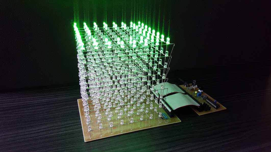 Fig. 1: LED cube as an equalizer.
The design of the cube is an extension of the previous version and has the same base – integrated circuits and a control microcontroller (MCU) from the same family. The cube is controlled using an ATmega328P microcontroller from Atmel. The individual LEDs, specifically their cathodes, are directly connected to the LED drivers TLC5922. The advantage of LED drivers is the constant current setting for individual LEDs. Each TLC5922 IC has 16 outputs for LEDs, the circuits can be chained to increase the number of outputs. The cube contains 64 LEDs (8 x 8) in one layer, thus 4 TLC5922 ICs are needed to control the LEDs in one layer. Additionally, the current of individual pins can be controlled to adjust the brightness of the LEDs, which is used in some lighting effects. The cube has 8 layers. The anodes of all LEDs in one layer are interconnected and connected to a pair of transistors that supply voltage to the layer and allow it to light up. Considering the current for LEDs is 20mA, the current consumption when all LEDs in one layer are lit is 64 x 20mA = 1.28A. The collector current for the used BC639 transistor is a maximum of 1A, so a Darlington pair of transistors was used. If we wanted to light up the entire cube (512 LEDs), the cube would need a current of 512 x 20mA = 10.24A. This is a relatively large current, which would place increased demands on the power supply and used components. To minimize current consumption, we utilize the persistence of human vision – the image remains on the retina for a certain time, so blinking can be converted into a continuous image. The cube is therefore lit up layer by layer, meaning only one layer with 64 LEDs is active at a time. If we want to light up the entire cube, we need to gradually light up the LEDs of the entire layer at a speed that the eye cannot perceive. The human eye does not notice the switching layers, so we have the impression that the entire cube is lit. The cube is made up of two separate PCBs, interconnected by two flat cables. The first PCB contains all the circuits needed to control the cube, and the second only contains the LEDs and connectors for connecting the flat cables. The advantage of separation is that we can create more cubes with different colored LEDs without the need to purchase additional integrated circuits to control the cube.
Circuit Description
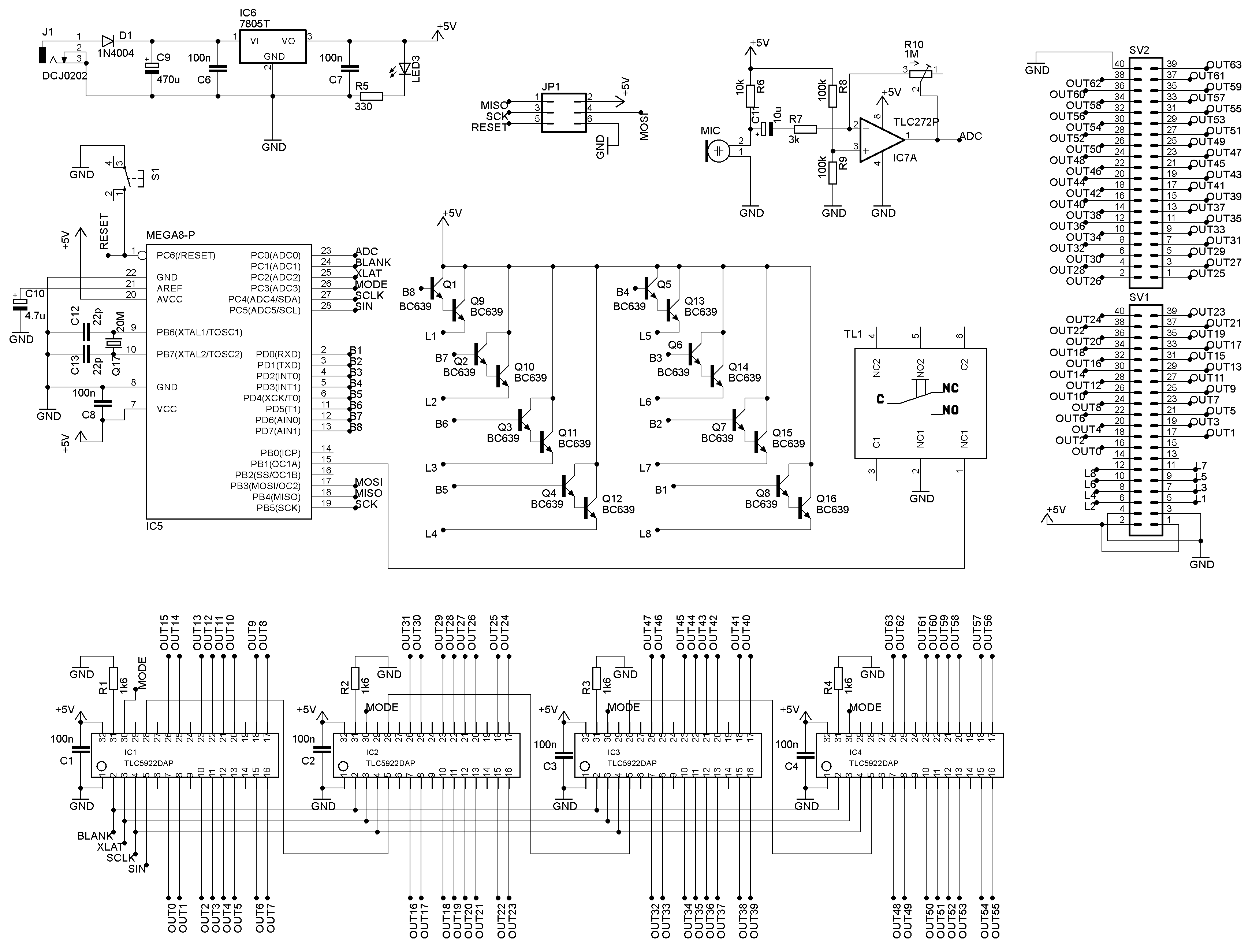 Fig. 2: Electrical schematic.
The device is powered by a 12V adapter, which is connected via a pin connector to the DCJ0202 socket. It is possible to use an adapter with a different voltage depending on the regulator IC6 used (for 78S05 it is 7-25V). Diode D1 protects against polarity reversal of the power supply. Using the 7805 regulator (IC6), the input voltage is stabilized to 5V. I used the 78S05 regulator for a current draw of up to 2A, a regulator for lower current may not be sufficient. Diode LED3 indicates the presence of 5V voltage. The stabilized 5V power supply from the IC6 output is used to power the microcontroller (IC5) and the LED drivers (IC1 - IC4). The core of the entire device is the 8-bit AVR microcontroller ATmega328P (IC5). The board has a JP1 connector for programming the microcontroller via the ISP interface (MISO, MOSI, SCK, RESET) without removing the MCU. The MCU is clocked at 8 MHz (note, the default value is 1 MHz, you need to change the CKDIV8 fuse when programming the MCU). The external crystal Q17 in the schematic and PCB design is only for increasing the MCU clock frequency and further experimentation. Therefore, crystal Q17 and capacitors C12 and C13 are not necessary. The MCU reset is triggered by briefly pressing the S1 button. Outputs PD0 to PD7 are connected to the bases of NPN transistors Q1 to Q8, which in a Darlington pair configuration with transistors Q9 to Q16 activate the individual layers of the cube. The emitters of transistors Q9 to Q16 are connected to the anodes of the LEDs in the given layer L1 to L8. MCU outputs PC0 to PC5 are used to control the LED drivers (IC1 - IC4). The output labeled SIN contains data for lighting up individual LEDs connected to outputs OUT0 to OUT63. A 64-bit code (1 bit for 1 LED) is sent over SIN. If a bit in SIN is 1, the LED lights up; otherwise, it does not. The SCLK output is a clock pulse for IC1 - IC4. With each rising edge of SCLK, a bit from SIN is written into the shift register of IC1 to IC4. When a logic high is applied to XLAT, the values from the shift register appear on the outputs of IC1 to IC4. The BLANK output is used for forced shutdown of all outputs. The MODE output selects the LED driver mode. The output current for LEDs is set using resistors R1 to R4. The current value must be set according to the LEDs used. I used clear green LEDs with a typical current of 20 mA and a brightness of over 10000 mcd. I set the current to 31 mA because the microcontroller program blinks the LEDs; they never light continuously, so there is no risk of LED damage since they can withstand much higher current short-term. It is advisable to set the current value above the typical value because the brightness of the LED decreases with blinking, and setting a higher value ensures optimal brightness. The current is set using resistors R3 and R4 according to the following relationship:
where VIREF is typically 1.24 V. For a current of 31 mA, resistors R1 - R4 have a value of 1.6 kΩ.
An electret microphone is connected to the first channel of the microcontroller's AD converter via an amplifier. The operational amplifier IC7 is in an inverting amplifier configuration. The microphone gain can be adjusted using the resistive trimmer R10, thereby setting the cube's sensitivity to ambient sound intensity. The TL1 button with a latch switches between two cube modes: light sequence or microphone input.
The control part PCB is shown in Fig. 3. It is a single-sided PCB. The use of SMD components could not be avoided because the TLC5922 integrated circuits are only manufactured in SMD form. To simplify the design and save space on the board, I added a few SMD capacitors and resistors on the trace side.
 Fig. 3: Control part PCB (trace side). Dimensions 134.6 x 74.9 mm.
Fig. 4 shows the component placement on the component side and Fig. 5 on the trace side.
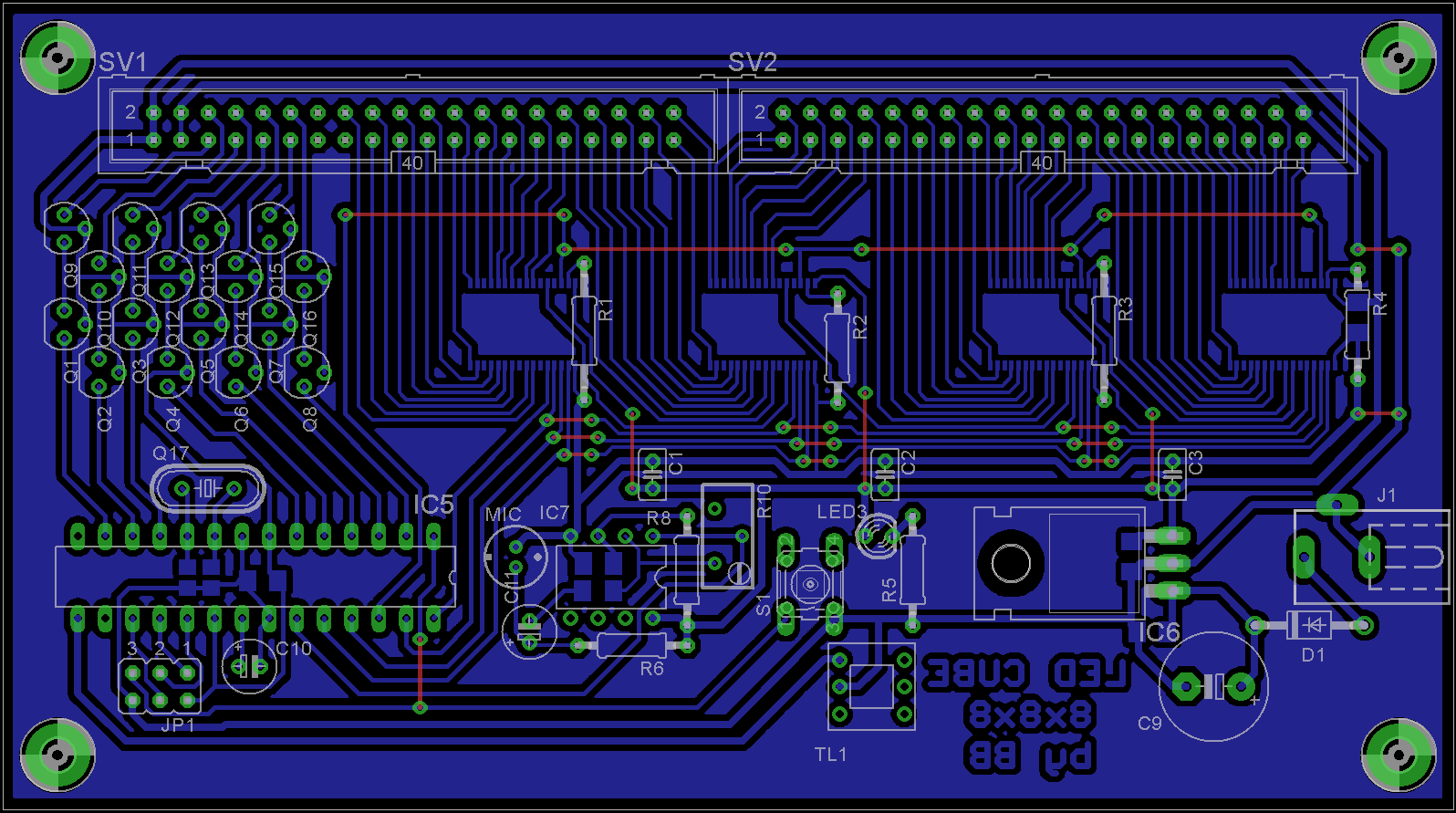 Fig. 4: Component placement on the component side.
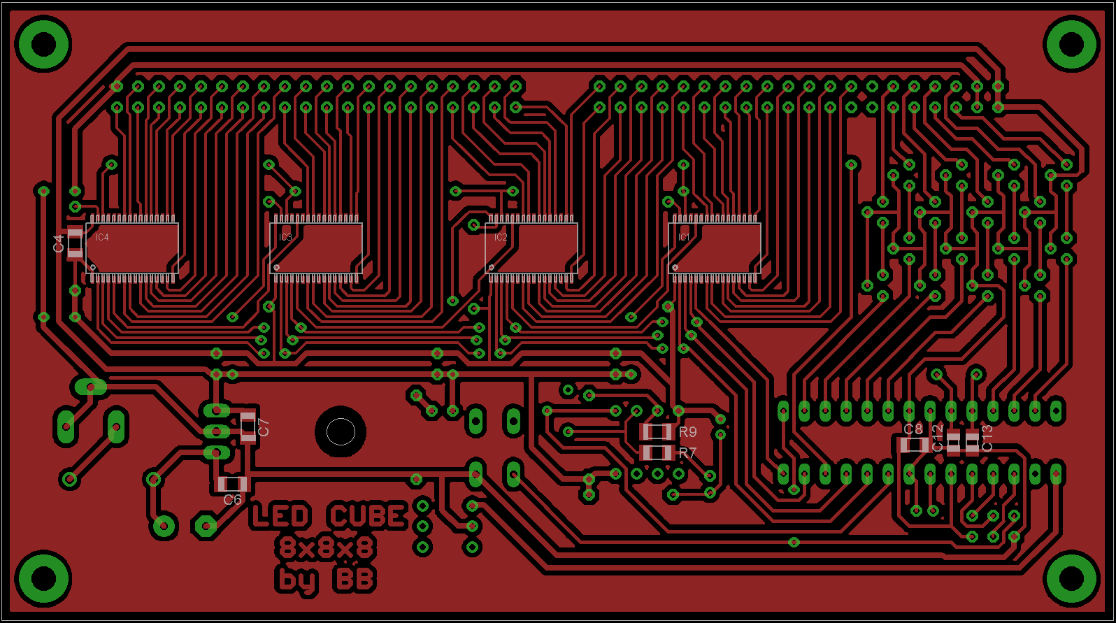 Fig. 5: Component placement on the trace side.
The circuit diagram for the PCB connecting the LEDs is shown in Fig. 6. The diagram includes 40-pin connectors SV3 and SV4 for connecting to the control PCB (SV1 and SV2) using a flat cable. It also includes pads PAD1-PAD64 for soldering the cathodes of individual LEDs and pin headers (JP2 and JP3) for connecting the cube layers L1-L8. Apart from the mentioned connectors and wire jumpers, the board does not contain any components. Some longer jumpers can be replaced with zero-resistance resistors. The PCB is shown in Fig. 7, and the component placement on the board is shown in Fig. 8.
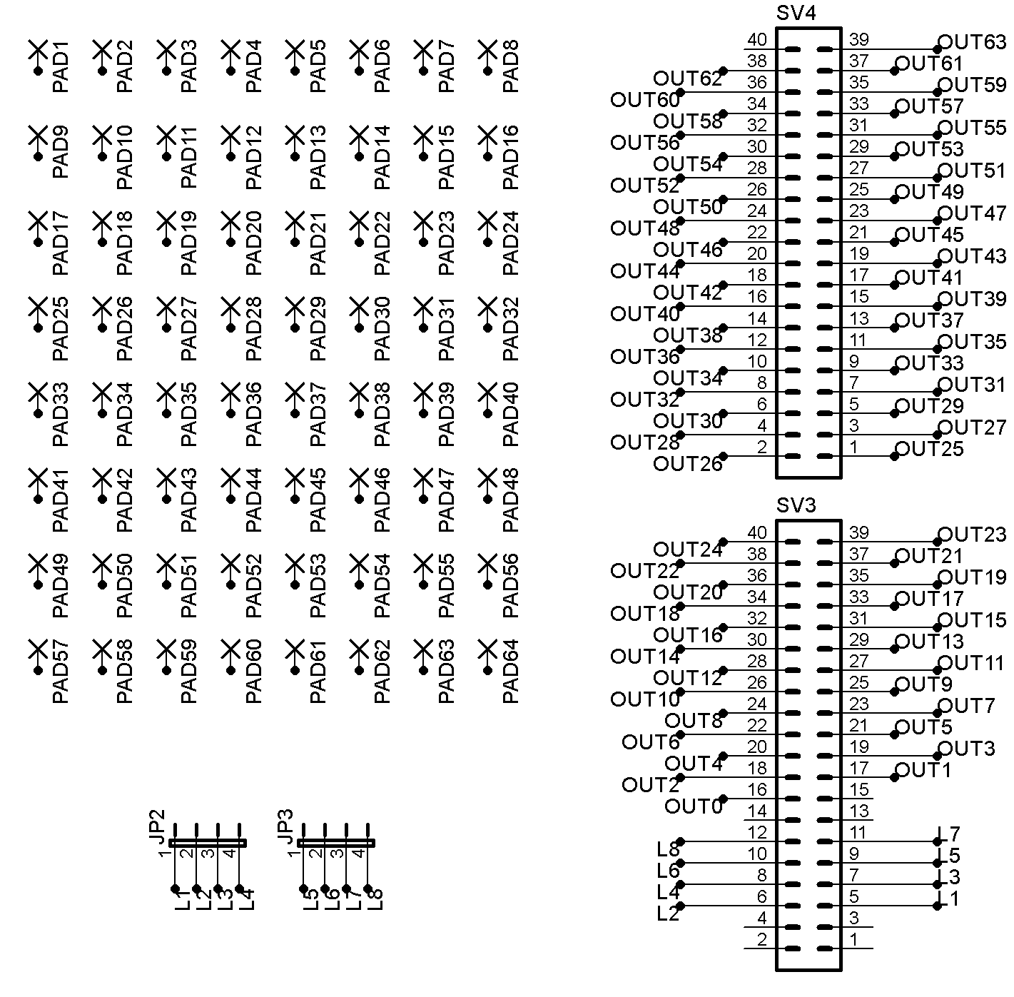 Fig. 6: Circuit diagram for the LED cube PCB.
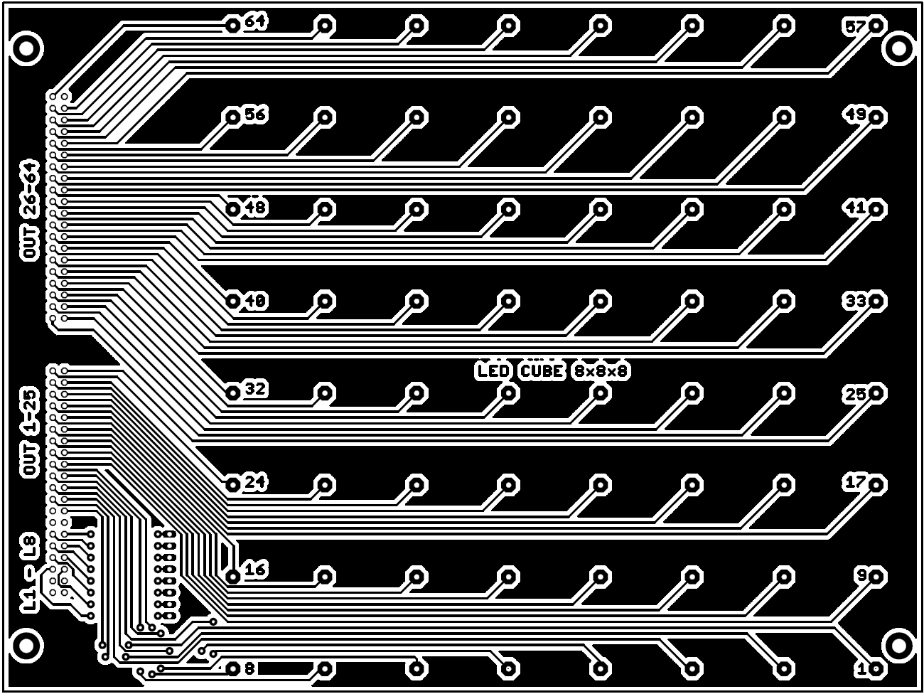 Fig. 7: PCB for connecting LEDs (trace side). Dimensions 200 x 150 mm.
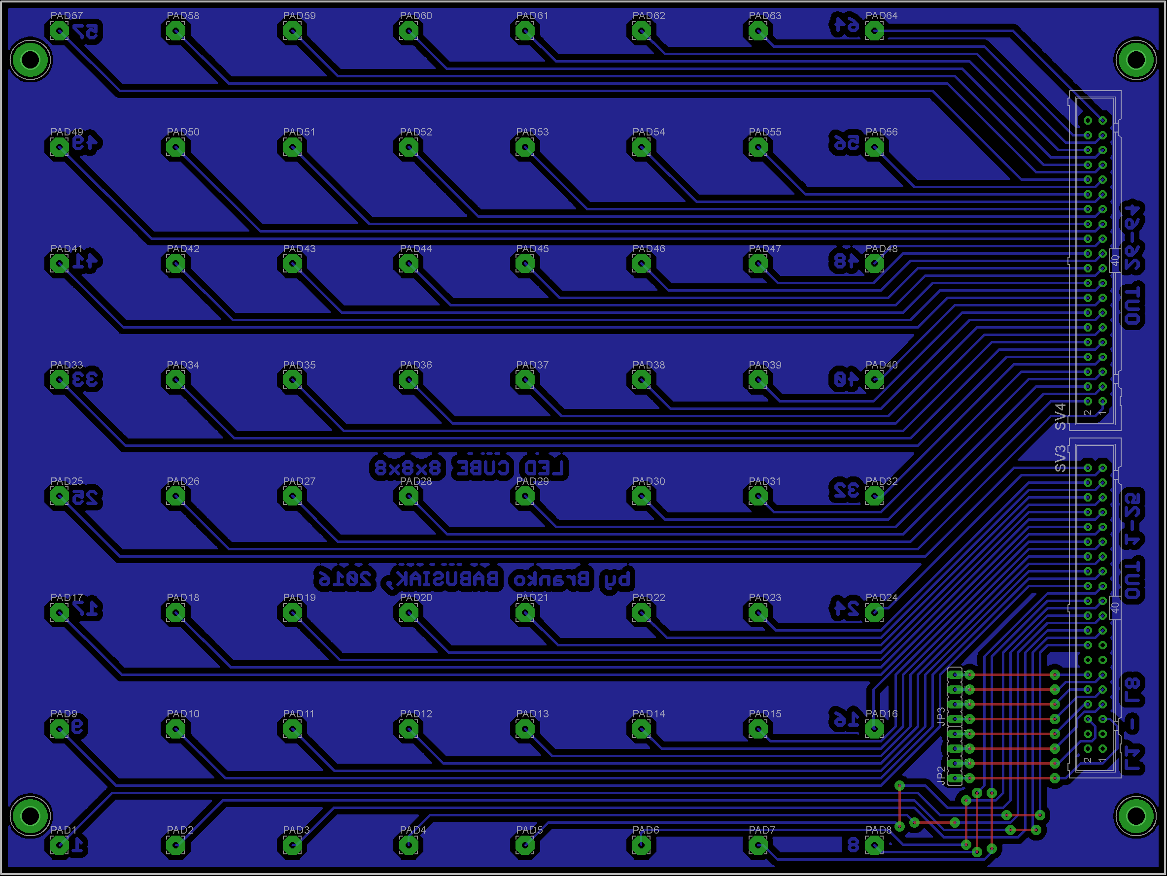 Fig. 8: Component placement on the component side of the PCB.
Construction of the Cube
The cube is built layer by layer, which are then soldered together. I used clear LEDs with a diameter of 5 mm, spaced 2 cm apart for constructing the cube. To maintain the distance between the LEDs, they were placed in pre-drilled holes in a wooden board (Fig. 9). The image also shows the method of bending all the LEDs except for those at the left end of the row. The anodes in each row are soldered together. A detailed view of the end of each row is shown in Fig. 10.
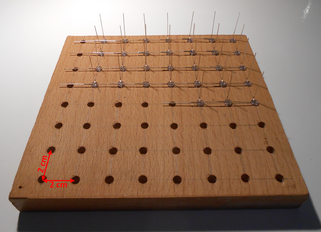 Fig. 9: Placing LEDs into pre-drilled holes.
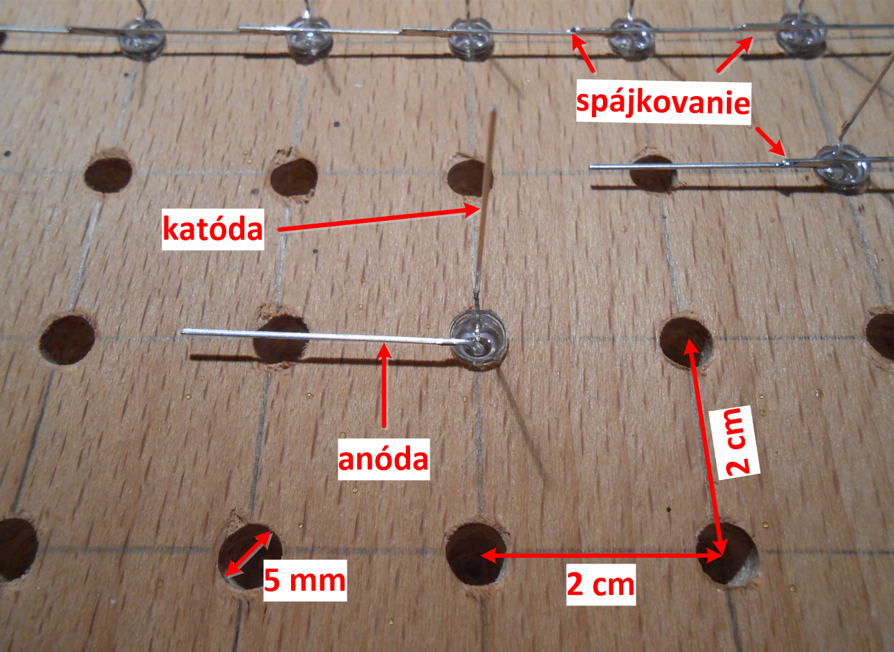 Fig. 10: Detailed view of the row ends.
To keep the layer in shape, it needs to be reinforced by columns. The reinforcement is done using a straight, sturdier wire soldered in the direction of the columns. The protruding ends of the wire are cut off after soldering. It is important that the wire does not touch the cathodes of the LEDs (Fig. 11). The layer has one common lead, representing the connection of all the LED anodes in the layer.
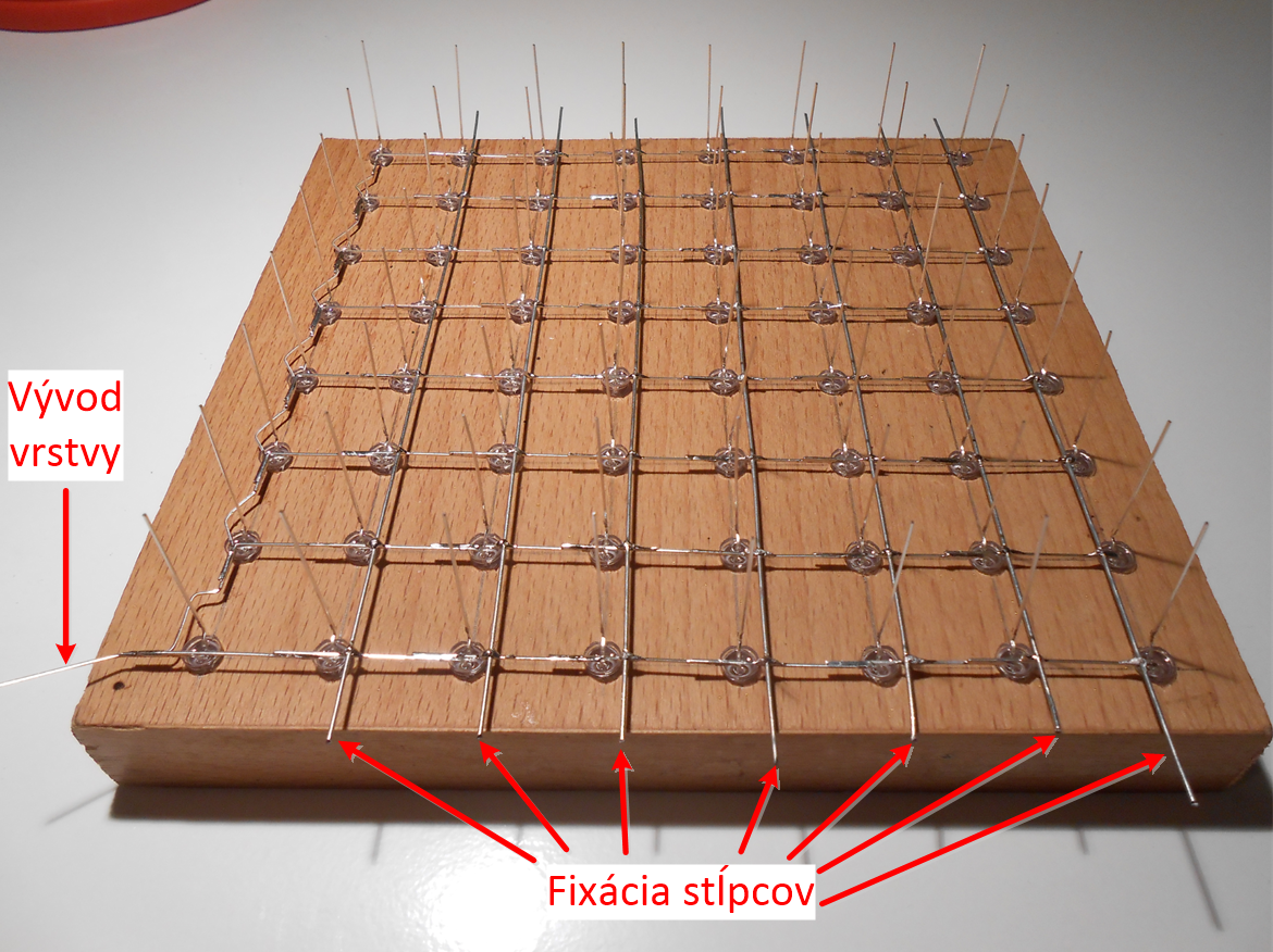 Fig. 11: View of the finished layer.
The finished layer can be placed into the PCB (Fig. 12) so that the layer's lead points to the pin headers JP2 and JP3. Above this layer, place the next layer with the same orientation of the lead and solder all the LED cathodes above each other. It is best to solder the LED cathodes around the perimeter first, then work inward. When soldering, ensure that the LEDs are in one plane (height), otherwise, the cube will look deformed. Continue this process up to the top eighth layer. The final step is to connect the leads of each layer to the pin headers JP2 and JP3. The connection is shown in Fig. 12. The connection is made using a thin, stripped wire that is unobtrusive.
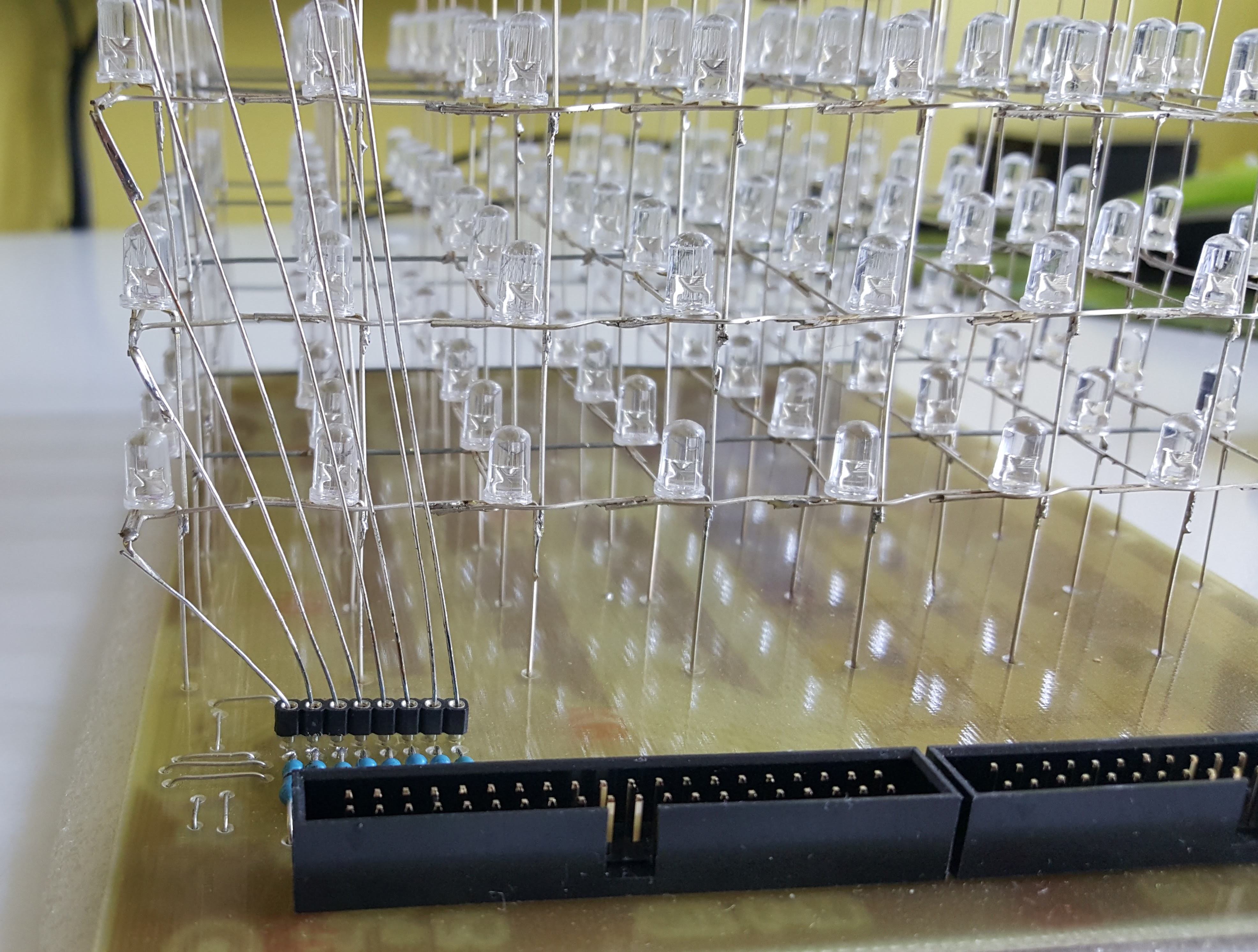 Fig. 12: Connecting the layers.
Bringing the Cube to Life
The cube should work immediately after connecting an external power source and correctly programming the microcontroller. The connected power supply is indicated by LED3. The microcontroller code contains various light sequences that play in a loop. The light sequences allow you to verify that all the LEDs were soldered correctly. If the cube does not work on the first try, check the connections for breaks or bridges, or if you forgot to insert any wire jumpers. The voltage regulator heats up because a relatively large current flows through it, so avoid touching the regulator to prevent burns. I recommend adding a heatsink to the regulator for better heat dissipation.
Conclusion
The assembled LED cube is an excellent lighting accessory for a room in the dark or low light. The total cost of the LED cube mainly depends on the LEDs used. Clear and frosted LEDs of various colors and sizes can be used. By pressing the TL1 button, you can change the cube's mode. In the first mode, the cube repeatedly plays programmed light sequences, and in the second mode, the cube lights up based on the intensity of the captured sound. The sensitivity of the cube can be adjusted by turning the trimmer resistor. Placing the cube near a speaker creates an effective sound equalizer. You can view videos of the finished cube here:
Downloads
EAGLE - PCB Design for Control PartEAGLE - PCB Design for Cube Base
Program for ATmega328P Microcontroller
Source Code in C Language
LED Configurator (64-bit Code Generator for LED Layer)