")
")

This article describes the process of creating an LED cube, which is an excellent visual accessory, especially in low light. Each edge of the cube contains 5 LEDs, and the entire cube consists of 125 LEDs (Fig. 1). The cube can be connected to the PC's USB port, through which individual light sequences can be configured. When connected to a PC, the cube can respond to various stimuli, e.g., it can light up and blink according to the currently playing music.
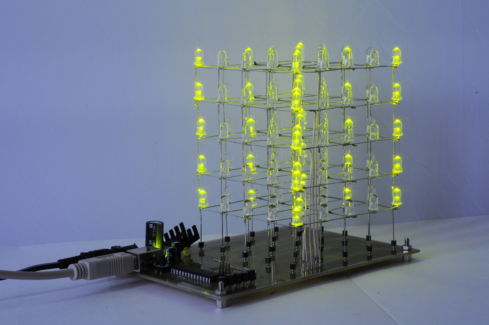 Fig. 1: LED cube with USB interface.
There are many links on the internet for creating LED cubes of various sizes. Most instructions and schematics share the same principle of controlling the cube. They only differ in the integrated circuits and microcontroller used to control the cube. I used the ATmega88A microcontroller from Atmel to control the cube and added control via the PC's USB port. The LEDs are not directly connected to the microcontroller outputs because it doesn't have that many pins, and it wouldn't handle such a current load. Controlling 125 LEDs individually would be very impractical in terms of current consumption and wiring 125 cables to each diode. The cube is controlled by utilizing the persistence of vision – the image remains on the retina of the eye for a while, making it possible to transform blinking into a continuous image. Therefore, the cube is controlled layer by layer, meaning that only one layer, containing 25 LEDs, is active at a time. For example, if we want to light up the entire cube, we need to light up the LEDs of the entire layer and quickly switch between layers. The human eye doesn't notice the switching of layers, so it appears that the entire cube is lit. The LEDs in each layer are turned on and off using two TLC5922 LED drivers from Texas Instruments. Each TLC5922 IC has 16 LED outputs, and the circuits can be chained to increase the number of outputs. To control 25 LEDs, two circuits are needed, with 7 outputs of one circuit remaining unconnected. The advantage of LED drivers is the ability to set a constant current for each output. Additionally, the TLC5922 can control the current of each output individually, but this feature is not yet used for cube control.
Connection Description
The connection diagram is shown in Fig. 2. The device is powered by a 12V adapter, which is connected with a pin connector to the DCJ0202 socket. It is possible to use an adapter with a different voltage depending on the stabilizer used (for 78S05, it is 7-25V). Diode D1 protects against reversing the power supply polarity. Using the 7805 stabilizer (IC5), the input voltage is stabilized to 5V. I used the 78S05 stabilizer for a current draw of up to 2A. The D3 LED indicates the presence of 5V voltage. The stabilized 5V power supply from IC5 output is used to power the microcontroller (IC3) and LED drivers (IC1, IC2). The USB<->UART converter FT232RL is powered from the USB port. The PC is connected to the device via a USB B connector (X1). For better noise filtering of the power supply through USB, a ferrite core is used. The outgoing and incoming communication through USB is indicated by LEDs LED1 (yellow) and LED2 (red). In addition to the data lines TD and RD, auxiliary lines RTS and DSR are also provided. The core of the device is the 8-bit AVR microcontroller ATmega88A (IC3). The JP31 pins are provided on the board for programming the microcontroller via the ISP interface (MISO, MOSI, SCK, RESET) without removing the MCU. The MCU is clocked by an 8 MHz internal crystal. An external crystal Q1, included in the schematic and PCB design, is only for experimentation with a different clock frequency. Therefore, Q1 and capacitors C10 and C11 are not necessary. The MCU is reset by briefly pressing the S1 button. Outputs PD3 to PD7 are connected to the bases of NPN transistors Q1 to Q5, which activate individual layers of the cube. The emitters of transistors Q1 to Q5 are connected to the anodes of the LEDs in the respective layers. The MCU outputs PC0 to PC4 control the LED drivers (IC1 and IC2). The output labeled SIN contains data that lights up individual LEDs connected to the holes OUT0 to OUT24. The cathodes of the LEDs are connected to OUT0 to OUT24. A 32-bit code is transmitted via SIN. The highest 7 bits are unused, and the remaining 25 bits control the 25 LEDs in each layer. If a bit in SIN has a value of 1, the LED lights up; otherwise, it doesn't. The SCLK output represents the clock pulse for IC1 and IC2. With each rising edge of SCLK, a bit from SIN is written into the shift register of IC1 and IC2. When a logic high is applied to XLAT, the values from the shift register appear on the outputs of IC1 and IC2. The BLANK output is used to forcibly turn off all outputs. The MODE output is used to select the LED driver's mode. The current of the outputs is set using resistors R3 and R4 connected to IC1 and IC2. The current value should be set according to the LEDs used. I used green LEDs with a typical current of 25 mA and a maximum peak current of 140 mA. I set the current to 31 mA because the microcontroller's designed program makes the LEDs blink, they never stay continuously lit, so there is no risk of damaging the LEDs. It is advisable to set the current above the typical value because the brightness of the LED decreases when blinking, and setting a higher value ensures optimal brightness. The current is set using resistors R3 and R4 according to the following relationship:
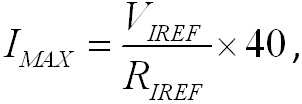
where VIREF is typically 1.24 V. For a current of 31 mA, R3 and R4 have a value of 1.6 kΩ.
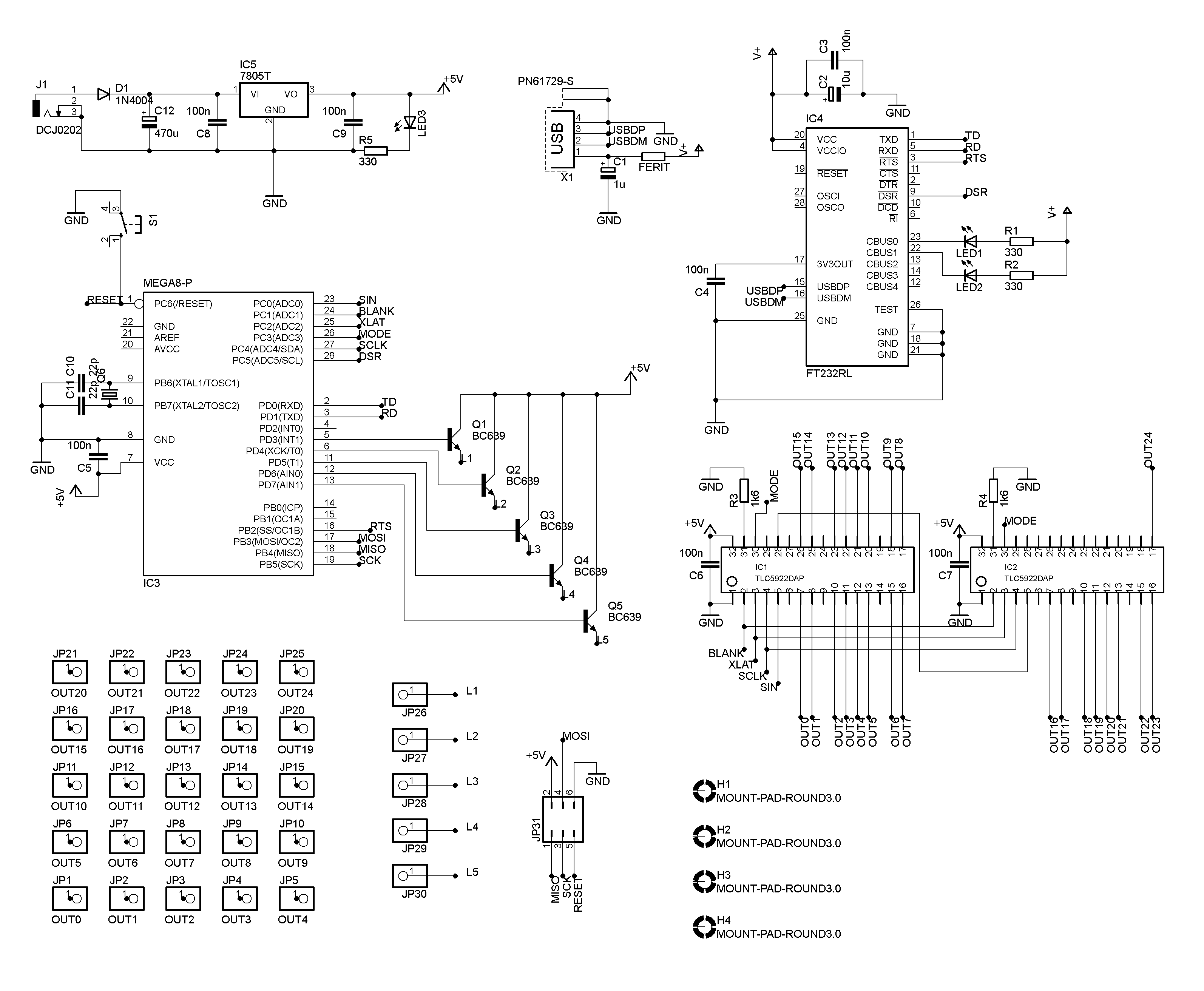 Fig. 2: Connection diagram.
If you want to write your own program for the microcontroller, I recommend temporarily increasing the value of resistors R3 and R4 so that the current through the LED does not exceed the typical value. This will prevent damage to the LED in case of continuous lighting for an extended period.
The printed circuit board is shown in Fig. 3. It is a single-sided PCB. Figs. 4 and 5 show the component placement. The use of SMD components was unavoidable because the FT232RL converter and TLC5922 integrated circuits are only available in SMD versions. A few SMD capacitors and resistors were added on the trace side to simplify the design and save space on the board. The LED network in the shape of a cube is inserted into the pre-prepared holes JP1-JP25. The anodes of the diodes in each layer are interconnected and connected by a wire to holes JP26-JP30.
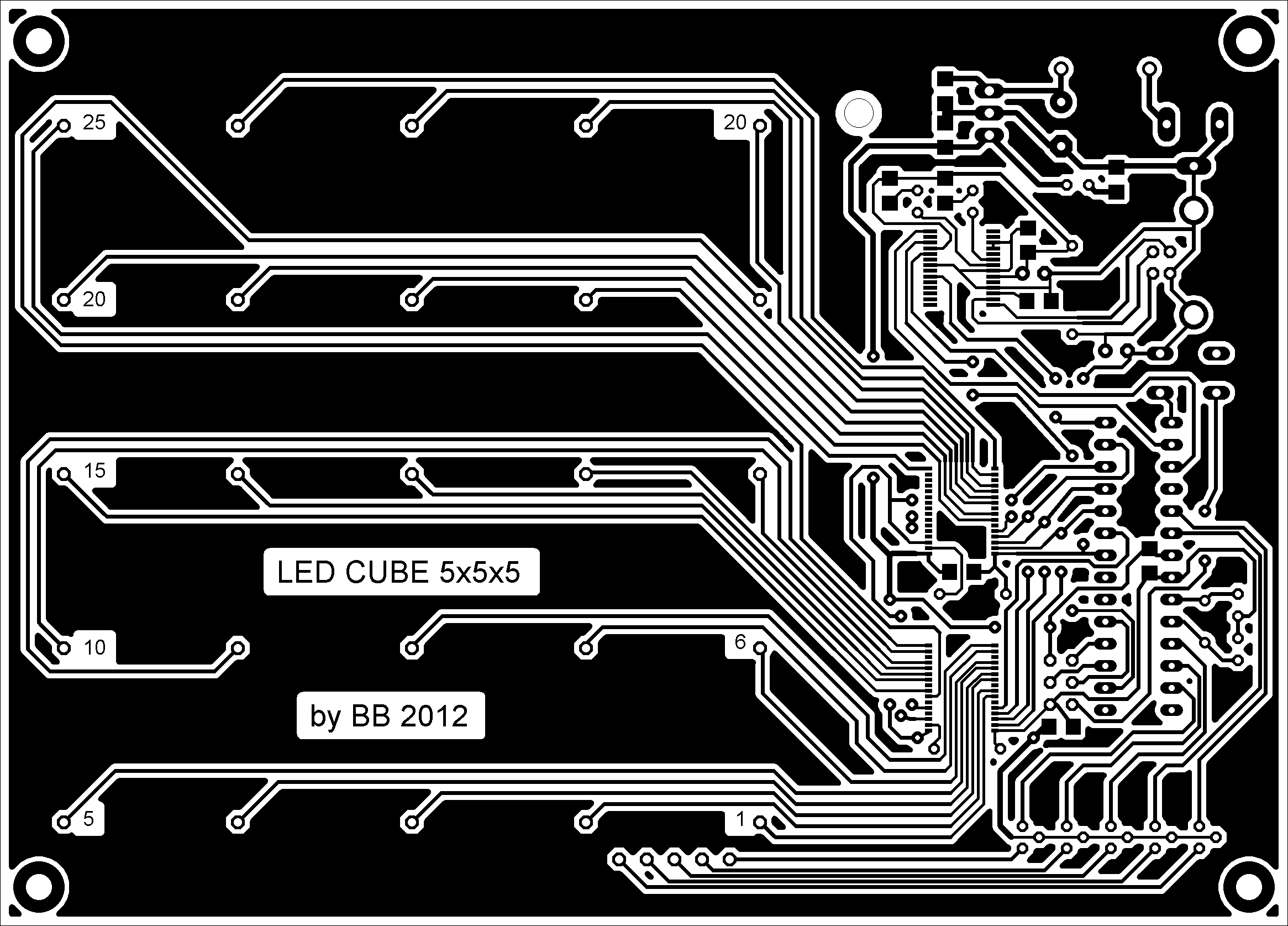 Fig. 3: PCB (trace side). Dimension 14.8 x 10.7 cm.
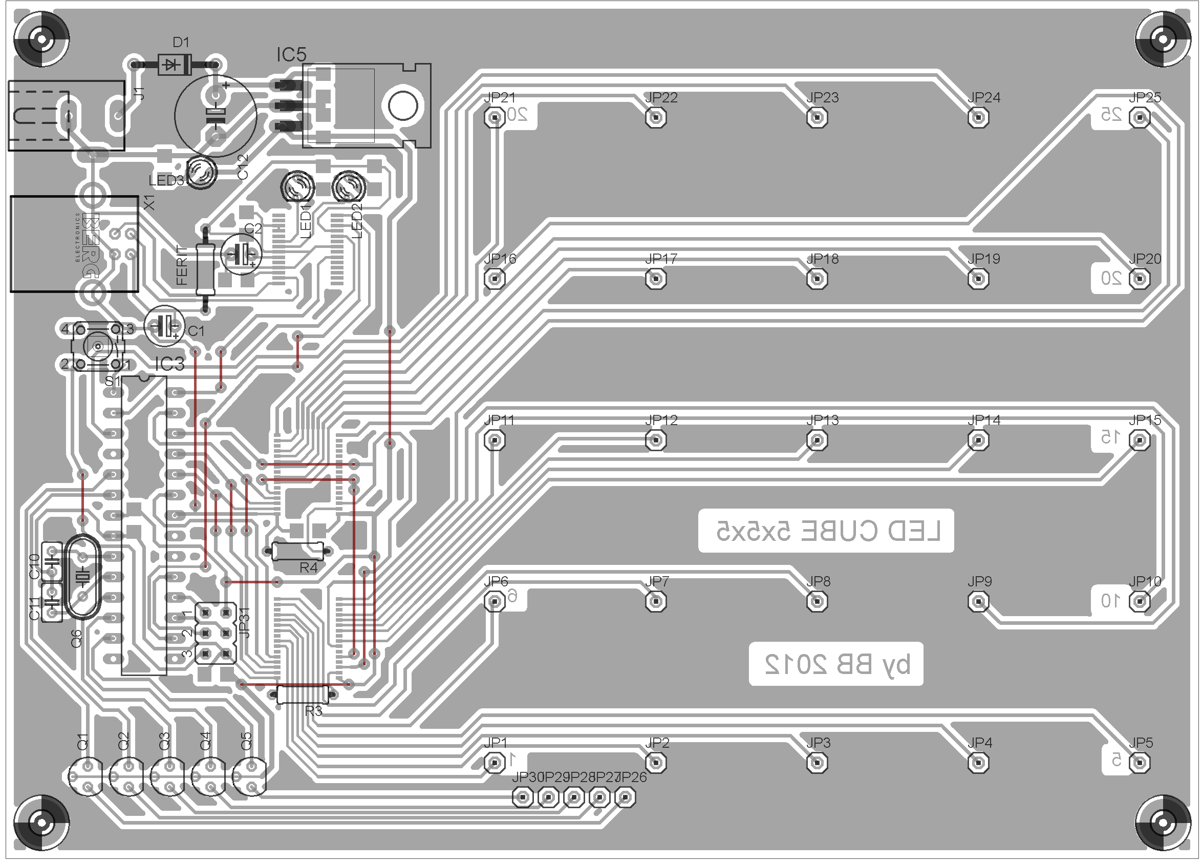 Fig. 4: Component placement. Component side.
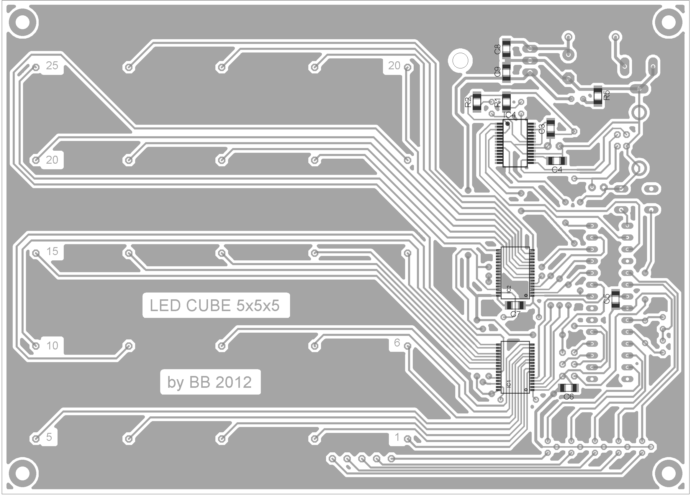 Fig. 5: Component placement. Trace side.
Construction of the Cube
For the construction of the cube, I used clear green LEDs with a diameter of 5mm. The LEDs in the layers are spaced 2 cm apart. To ensure these distances are maintained, I pre-drilled holes with a diameter of 5 mm in a wooden board. The holes are arranged in a 5x5 square grid with a grid density of 2 cm (Fig. 6).
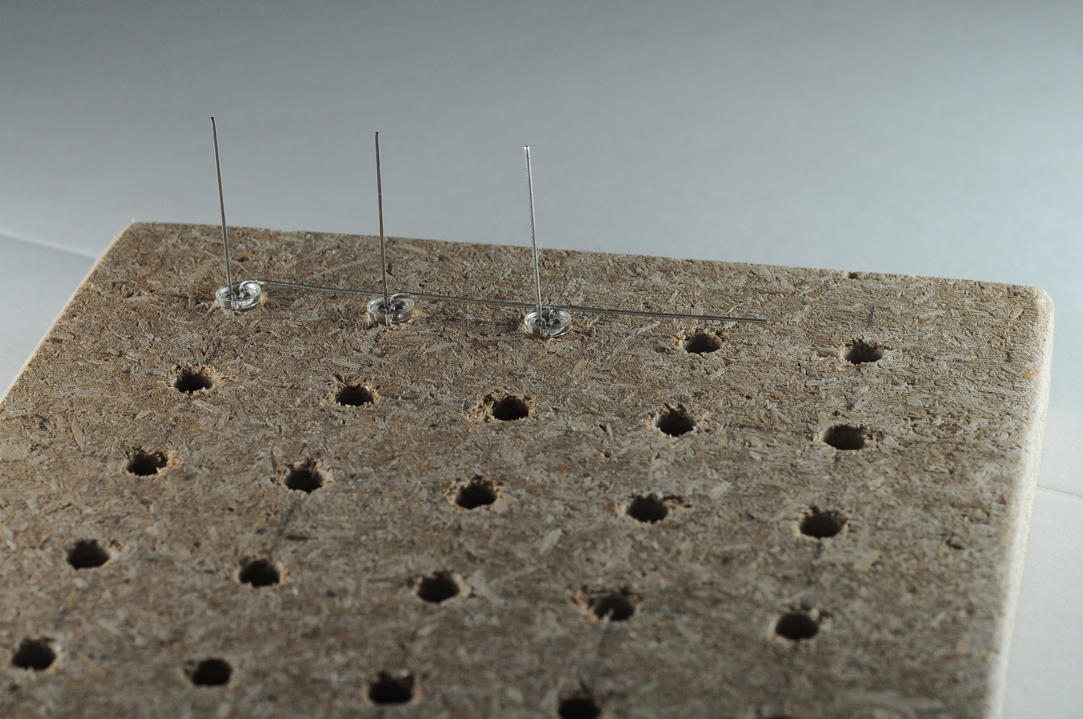 Fig. 6: Placing the LEDs in pre-drilled holes for soldering.
Before soldering, I bent the leads of each LED as shown in Fig. 7.
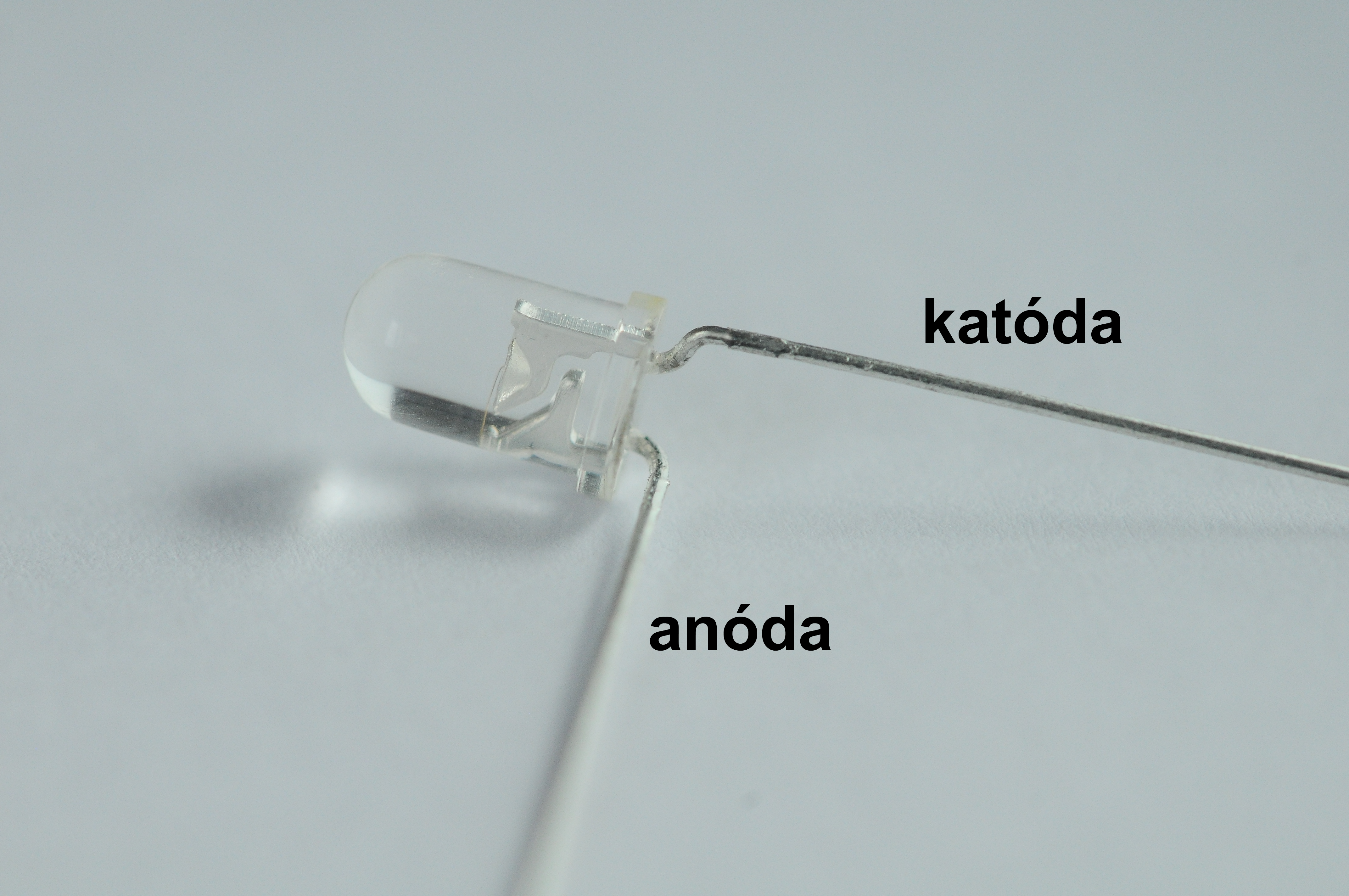 Fig. 7: LED with bent leads.
I placed the modified LEDs into the pre-drilled holes and soldered their anodes together (Fig. 8).
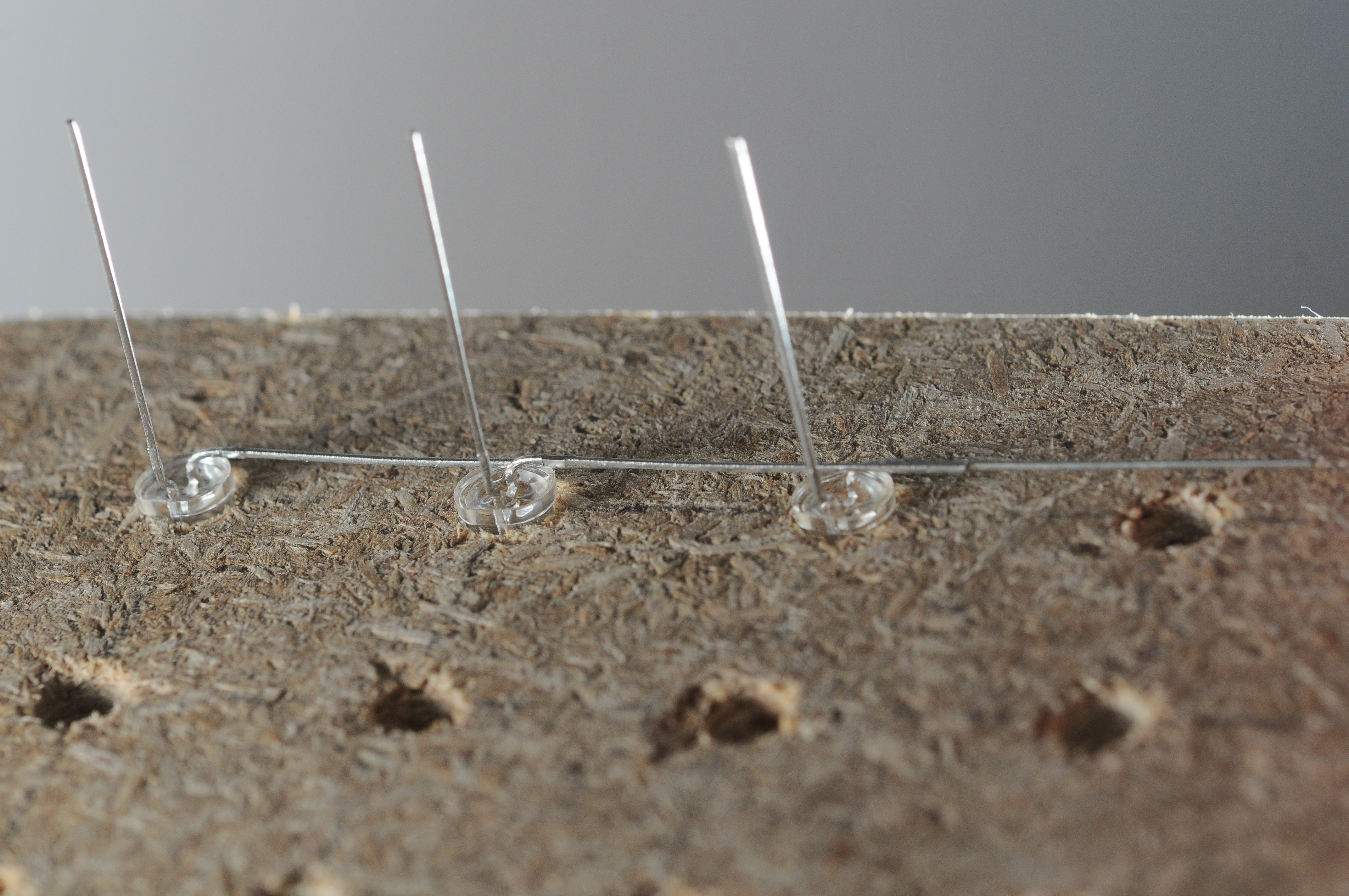 Fig. 8: Detail of placing LEDs into pre-drilled holes.
I added two wire connections to hold the layer's shape and prevent deformation. This way, I created five separate layers. The layers are then connected by soldering all the cathodes of the LEDs that are above each other. The detail of the LED connections is shown in Fig. 9.
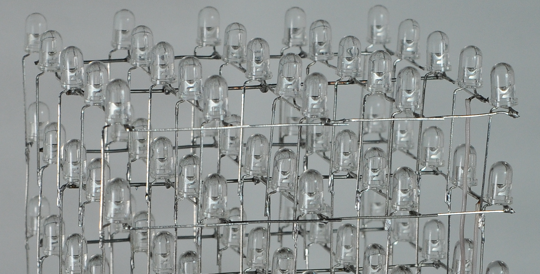 Fig. 9: Detail of soldering LEDs.
The whole cube is then inserted into holes JP1 to JP25. The holes were created from a breakable female pin header. Each layer is then soldered with a wire, and its end is gradually inserted into JP26 for the top layer to JP30 for the bottom layer. Creating the LED cube takes quite a bit of time, but it's essential to carefully bend each lead and then solder to ensure the resulting cube is not deformed.
Activating the Cube
The first step is to upload the program to the microcontroller that lights up the individual LEDs. Besides uploading the program, the fuses must be correctly set. The fuse settings of the MCU are shown in Fig. 10.
 Fig. 10: Fuse settings in Atmel Studio environment.
The cube should work immediately after connecting an external power source. The connected power voltage is indicated by LED3. The microcontroller has a code uploaded that contains various light sequences played in a loop. The light sequences help verify whether all the LEDs were soldered correctly. If the cube doesn't work on the first try, check the connections to see if there is a break or a short circuit, or if any wire connections are missing. The voltage regulator heats up because it carries a relatively high current (25 LEDs x 31 mA = 775 mA). Therefore, do not touch the regulator to avoid burns. I recommend adding a heatsink to the regulator for better heat dissipation. The cube can be controlled via a computer's USB port. For this purpose, software was created in the C# programming language to control the cube.
Controlling the LED Cube via USB Port
When the cube is first connected to the computer, a virtual serial port is installed. If the driver does not install automatically, download it from www.ftdichip.com. The serial line is set to a speed of 38,400 Baud, and data is sent as eight-bit with one stop bit. In case you want to create your control software, note that 32 bits (4x8 bits) are always sent to light up the cube. The lower 25 bits determine which LED in the layer should light up, and the highest three bits code which layer should be activated. To activate the first (top) layer, the highest bits have the value 001b, for the second layer 010b, for the third layer 011b, for the fourth layer 100b, and for the bottom layer 101b.
As already mentioned, when power is connected, the cube lights up according to the program uploaded in the microcontroller. After each run of the program, the state of the RTS line is checked. If we set RTS to one in the PC, the program from the microcontroller stops executing, and the cube will light up according to the data sent via the virtual serial port. To avoid waiting until the entire program from the MCU runs, press the RESET button on the board.
For convenient creation of light sequences as desired, software with an interactive and intuitive user interface was created in the C# programming language. If the program does not work after launch, you probably do not have the .NET Framework 4.0 installed on your computer. You can download the framework directly from the Microsoft website. The graphical user interface is shown in Fig. 11. The application is in English for broader use.
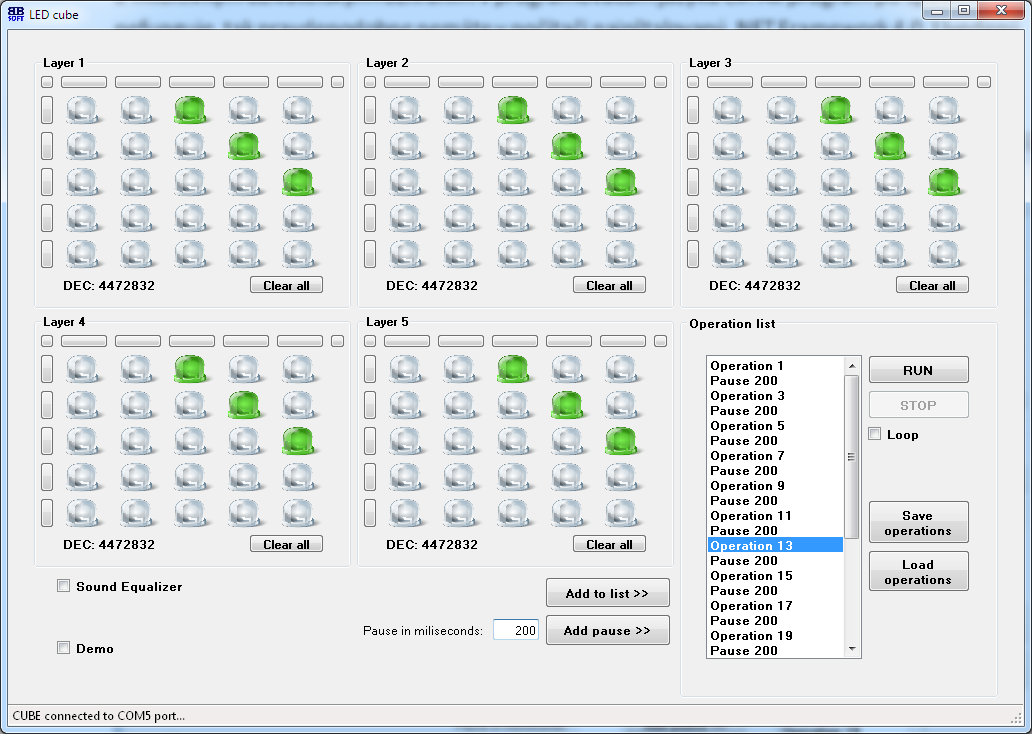 Fig. 11: Graphical user interface for controlling the LED cube.
Connect the LED cube to the power supply and the computer's USB port before launching the software. Upon launch, the software automatically detects which port the cube is connected to and sets the RTS line to a logical one. The status bar informs about successful connection. After pressing the RESET button on the PCB, one diagonal of the cube lights up. Clicking on the desired LED changes its color, and the change is immediately visible on the LED cube. The software allows lighting or turning off entire rows or columns by clicking the empty button at the beginning of the respective rows or columns. When the desired effect is achieved, add it to the sequence by clicking the Add to list button. A pause must be added for each scene in the sequence. The pause is specified in milliseconds and added to the sequence by clicking the Add pause button. Scenes and pauses in the sequence can be edited and deleted by right-clicking on the respective item. The Run button is used to play the sequence. To loop the sequence, check the Loop box. The Stop button is used to stop the looped sequence. The programmed sequences can be saved to a file with a *.cub extension and later loaded again. The application contains a checkbox for the Sound Equalizer. If this box is checked, the cube flashes according to the volume level of the currently playing music. When the Demo box is checked, the program from the MCU runs. To stop the demo sequence immediately, it is advisable to press the RESET button on the PCB after unchecking this box. A skilled programmer can create a custom program to alert them to various events, such as a new email, by flashing the cube.
Conclusion
The constructed LED cube is an excellent lighting accessory for a room in the dark and in low light conditions. The cube has a pre-programmed sequence of light effects that play immediately after connecting the power. By connecting the cube to a PC using a USB cable and using the created software, it is possible to create light effects as desired. The total cost of the LED cube mainly depends on the LEDs used. Clear and matte LEDs of various colors and sizes can be used. Finally, I would like to thank Barbora Martikáňová for taking quality photos of the LED cube used for this article.
List of Used Components
| C1 | 1 µF |
| C2 | 10 µF |
| C3 – C9 | 100 nF (SMD1206) |
| C10, C11 | 22 pF |
| C12 | 470 µF |
| D1 | 1N4004 |
| FERIT | Ferrite bead/core |
| IC1, IC2 | TLC5922DAP |
| IC3 | ATmega88A |
| IC4 | FT232RL |
| IC5 | 7805 |
| J1 | DCJ0202 (DC connector) |
| LED1 - LED3 | LED3MM |
| Q1 - Q5 | BC639 |
| Q6 | HC49/S (crystal) |
| R1, R2 | 330 Ω (SMD1206) |
| R3, R4 | 1k6 Ω |
| R5 | 330 Ω (SMD1206) |
| S1 | button |
| X1 | USB-B connector |
| LED (125x) | LED for the cube |
Downloads
EAGLE - Electrical Circuit DiagramEAGLE - PCB Layout
Program for ATmega88A Microcontroller
Source Code in C Language
Sequence Programming - Application for Windows OS