")
")
Setting and Clearing Bits in a Register
Programming an MCU is based on setting registers that perform specific functions. In the case of MCUs from the AVR family, which includes the ATmega328P, all registers are 8-bit. It is essential to know how to set a logical 1 or a logical 0 on the corresponding bit in the register. Setting a logical one is referred to as setting a bit, while setting a logical zero is called clearing a bit. Each register has its specific address. To simplify and clarify access to registers, a unique name is assigned to the register address. For example, the register PORTB has the address 0x05, but we access it using its name PORTB. The register names for the ATmega328P MCU are defined in the header file iom328p.h. The aforementioned PORTB is defined in this file as follows:
#define PORTB _SFR_IO8(0x05)
Note: SFR (Special Function Registers) are special registers intended for controlling the MCU’s peripheral circuits.
Similar to registers, individual bits are also assigned unique names. Below are the names of the individual bits for the PORTB register, which are listed in iom328p.h:
#define PORTB0 0
#define PORTB1 1
#define PORTB2 2
#define PORTB3 3
#define PORTB4 4
#define PORTB5 5
#define PORTB6 6
#define PORTB7 7
#define PORTB1 1
#define PORTB2 2
#define PORTB3 3
#define PORTB4 4
#define PORTB5 5
#define PORTB6 6
#define PORTB7 7
Based on the bit definitions above, when setting a bit, we do not use the bit's ordinal number but its name, which significantly improves code readability.
Let's demonstrate bit setting with a specific example. The ABB development board has 8 LEDs connected to the PORTB port. LED0 is connected to pin PORTB0, LED1 is connected to pin PORTB1, etc. Suppose the entire PORTB is set as output (DDRB=255) and we want to turn on LED3 (connected to PORTB3). We can do it as follows:
PORTB=0b00001000; //binary notation, not clear
A clearer method uses bit shifting, which immediately indicates which bit of the register we are setting:
PORTB=(1<<PORTB3); //left bit shift using the bit name
The notation is fine if we want to turn on LED3 and turn off all others. If LED0 was initially on, this command PORTB=(1<<PORTB3) would turn it off. If we want to turn on LED3 and keep the original state, the notation changes as follows:
PORTB|=(1<<PORTB3); //left bit shift using bitwise OR (|), retains the original state of other bits in the PORTB register
If we want to set a bit named BIT in a register named REG without affecting other bits, we use the following notation:
REG|=(1<<BIT); //setting a bit in a register
We will also demonstrate clearing a bit with an example. Suppose we have LED3 on (connected to PORTB3), which we want to turn off:
PORTB=0b00001000; //LED3 is on
PORTB=0b00000000; //turn off LED3 using binary notation, not clear
PORTB=0b00000000; //turn off LED3 using binary notation, not clear
The above notation is impractical because we need to know the exact position of the bit we want to clear, and we can easily make a mistake. If more LEDs are on, this notation would turn off all of them, which we do not want. To turn off LED3 without affecting the state of other LEDs, we use the following notation:
PORTB&=~(1<<PORTB3); //left bit shift using bitwise AND (&) and bitwise negation (~), retains the original state of other bits in the PORTB register
In general, if we want to clear a bit named BIT in a register named REG without affecting other bits, we use the following notation:
REG&=~(1<<BIT); //clearing a bit in a register
Checking the State of a Bit in a Register
To check the state of a bit in a register, bit masking using the logical AND (&) operation is used. We will demonstrate checking the state of a bit with a general example. The PIND register is used to check the state of a pin on port D if the corresponding register bit is configured as an input. For example, if we want to check the state of bit PIND3, we use the following notation:
if (PIND&(1<<PIND3)) {
//bit PIND3=1
} else {
//bit PIND3=0
}
//bit PIND3=1
} else {
//bit PIND3=0
}
Let's break down the above example in more detail. The result of the bit shift (1<<PIND3) is 0b0000 1000 in binary form. If we then use the bitwise AND (&) operation, we can get two different results depending on the state of bit PIND3, as shown in the image:
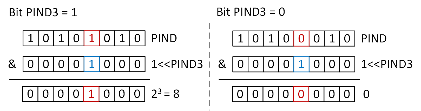
The if condition is met if the expression in parentheses evaluates to a positive non-zero value, so it is not necessary to specify that the value must be 8. Conversely, if bit PIND3 = 0, the result of the bitwise AND operation will always be zero, and the condition will not be met.
In general, if we want to check the value of a bit named BIT in a register named REG, we use the following notation:
if (REG&(1<<BIT)) {
//bit BIT=1
} else {
//bit BIT=0
}
//bit BIT=1
} else {
//bit BIT=0
}