Temperature and Humidity Measurement Using a One-Wire Interface Sensor
1. Theoretical Introduction
The DHT22 sensor is a very popular module designed for measuring temperature and relative humidity. This sensor is the successor to the DHT11, which features lower bit resolution and accuracy. Table 1 lists the key parameters of both sensors.
| Parameter | DHT11 | DHT22 |
|---|---|---|
| Range (Temperature) | (0 ÷ 50) °C | (-40 ÷ 80) °C |
| Accuracy (Temperature) | ± (1 ÷ 2) °C | ± 0.5 °C |
| Range (Relative Humidity) | (30 ÷ 90) % | (30 ÷ 100) % |
| Accuracy (Relative Humidity) | ± (4 ÷ 5) % | ± (2 ÷ 5) % |
| Supply Voltage | (3.3 ÷ 5) V | (3.3 ÷ 5) V |
| Resolution | 8-bit | 16-bit |
| Sampling Period | ≥ 1 s | ≥ 2 s |
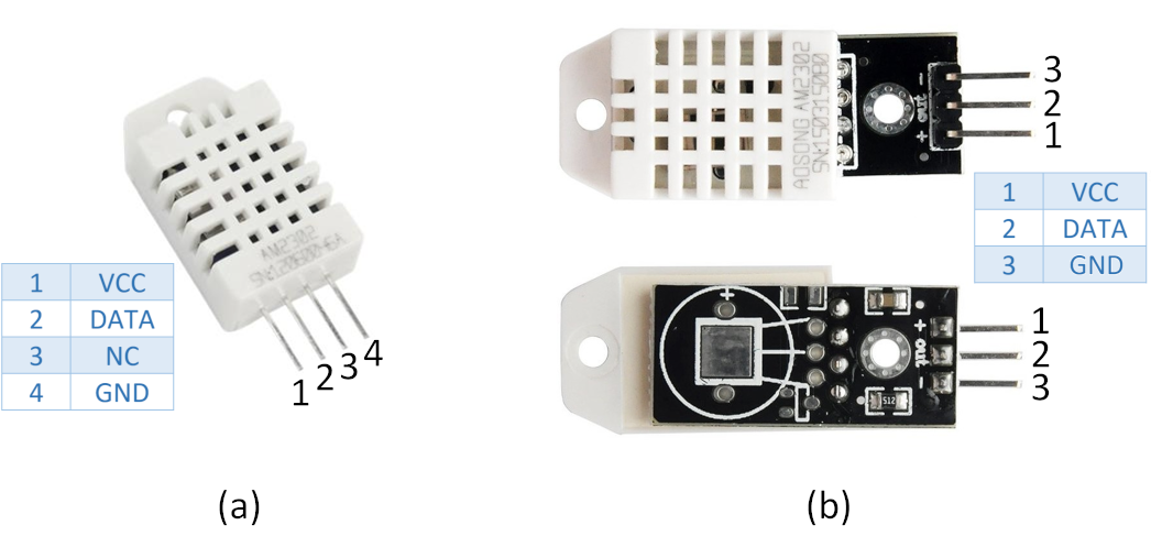
The DHT22 sensor is also marketed under the designation AM2302. The sensor is enclosed in a slotted plastic casing and features four pins, one of which is left unconnected (Fig. 1a). The sensor can also be purchased mounted on a breakout PCB with three pins (Fig. 1b), facilitating easy connection to other devices.
1.1 Communication Protocol
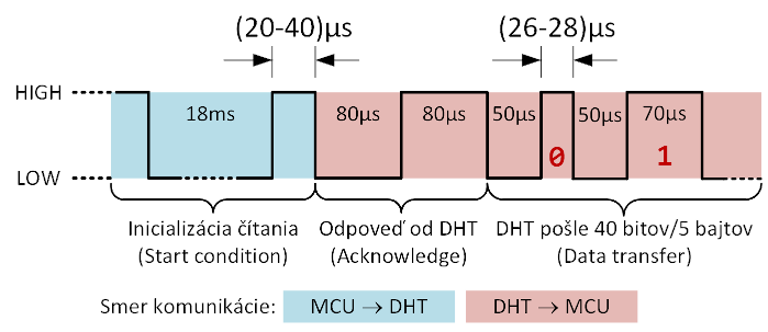
For communication, the sensor utilizes only a single line (DATA). A communication interface using only one wire is referred to as a one-wire interface or one-wire bus. The DHT22 sensor uses a proprietary communication protocol illustrated in Fig. 2. Communication is bidirectional over the DATA pin and is relatively straightforward. The idle state of the line is HIGH. For this reason, it is advisable to attach a pull-up resistor (4.7kΩ or 10kΩ) to this pin so the line remains pulled HIGH during inactivity. Communication initialization is triggered by the MCU pulling the line LOW for at least 18 ms. The MCU then releases or drives the line HIGH for (20–40) µs. This sequence represents the Start condition for the DHT sensor. The sensor responds with an Acknowledge signal consisting of a LOW level (80 µs) followed by a HIGH level (80 µs). After the acknowledgement, data transfer begins with the measured humidity and temperature values. The sensor transmits a total of 40 bits (5 bytes). Before each bit is sent, the line is pulled LOW for 50 µs. The bit value is then encoded by the duration of the subsequent HIGH level. If the HIGH pulse lasts (26–28) µs, the bit value is '0'. If it lasts 70 µs, the bit value is '1'. Communication concludes when the line returns to the HIGH idle state.
- Configure the MCU pin as an output.
- Send Start condition:
- Transition from HIGH (idle state) to LOW (18 ms).
- Transition to HIGH for (20–40) µs.
- Configure the MCU pin as an input with internal pull-up resistor.
- Wait for Acknowledge from the DHT. Expected MCU input sequence:
- LOW level (80 µs)
- HIGH level (80 µs)
- Receive data transfer (40 bits) of humidity and temperature:
- Each bit starts with a LOW level for 50 µs
- The subsequent HIGH level encodes the bit value:
- Duration (26–28) µs = bit '0' (LOW duration),
- Duration 70 µs = bit '1' (HIGH duration).
- Communication terminates by returning to the idle state at a HIGH level, maintained by the pull-up resistor.
The sequence described above can be repeated whenever updated relative humidity and temperature readings are required. According to the specification, new data must not be requested sooner than every 2 seconds; otherwise, the sensor may return invalid readings or fail to respond altogether.
1.2 Data Format
As mentioned previously, the sensor transmits 40 bits containing humidity and temperature information. The sensor's data packet format is shown in Fig. 3.
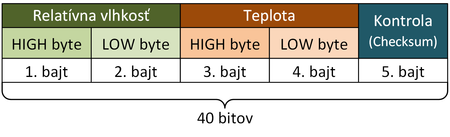
As seen in Fig. 3, the sensor first transmits 2 bytes containing humidity data, followed by 2 bytes containing temperature data, and finally a checksum byte used to verify data integrity.
The following example illustrates how the 2-byte temperature reading is converted into a temperature in [°C]. Suppose the bytes shown in Fig. 4 are read from the DHT22 sensor:
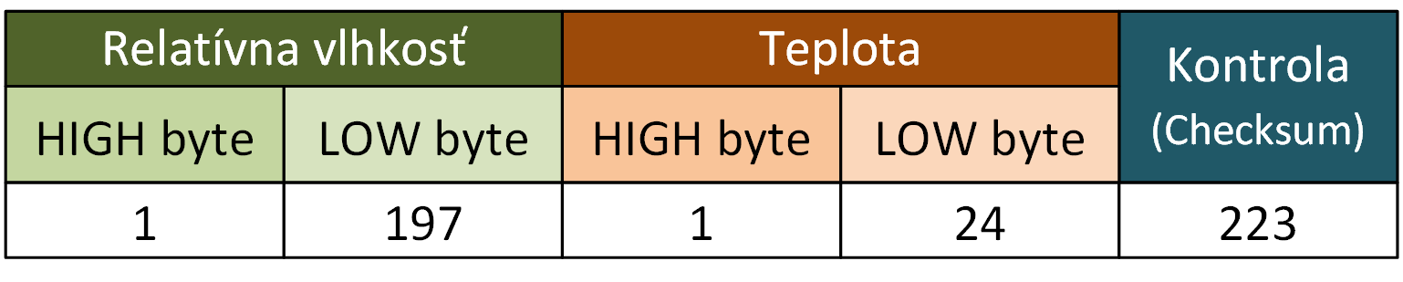
For clarity, we first convert the decimal byte values into binary. Next, we concatenate the binary numbers and convert them back into a single 16-bit decimal value. To obtain the temperature in °C, this decimal value is divided by 10. The procedure is summarized in Table 2.
| Numeral System | TEMPERATURE | |
| HIGH byte | LOW byte | |
| Decimal | 1 | 24 |
| Binary | 0b00000001 | 0b00011000 |
| Binary (16-bit) | 0b00000001 00011000 | |
| Decimal (16-bit) | 280 | |
| /10 | 28.0 °C | |
The same calculation procedure is applied to convert the relative humidity value, which is expressed in [%].
The checksum byte (5th byte) is the sum of the preceding four data bytes. Using this checksum, the MCU can verify data integrity directly upon reception. Note that the checksum byte operates within the range of 0 to 255 (8-bit roll-over). If the arithmetic sum of the four bytes exceeds 255, an overflow occurs. For example, if the arithmetic sum of the four bytes is 260, the resulting checksum byte value will be 4.
2. Equipment Used
- Hardware
- Mega Development Board 2 (MDB2)
- DHT22 temperature and humidity sensor
- PC
- Software
- MATLAB
- Microchip Studio
3. Schematic Diagram
4. Assignment Tasks
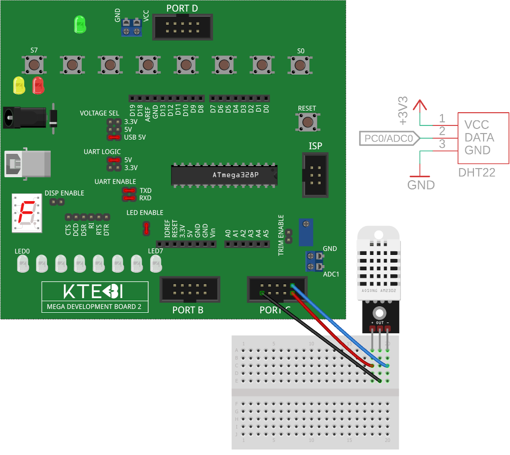
- Connect the DHT22 sensor to the MDB2 development board according to the wiring schematic (Fig. 5). Use USB power supply. The jumper configurations on the MDB2 are highlighted in red.
- Write an MCU firmware program in C to read relative humidity and temperature data from the DHT22 sensor. The acquired data will then be sent to the PC via UART. Implement the following parameters and functionality in the code:
- Sample humidity and temperature data from the sensor and transmit them to the PC every 2 s,
- Verify data integrity at the MCU level using the checksum byte,
- Set the UART baud rate to 19,200 Baud,
- Begin sending data to the PC only after receiving the character 'S', and stop transmission upon receiving the character 'X'. Use the UART receive interrupt to detect incoming characters,
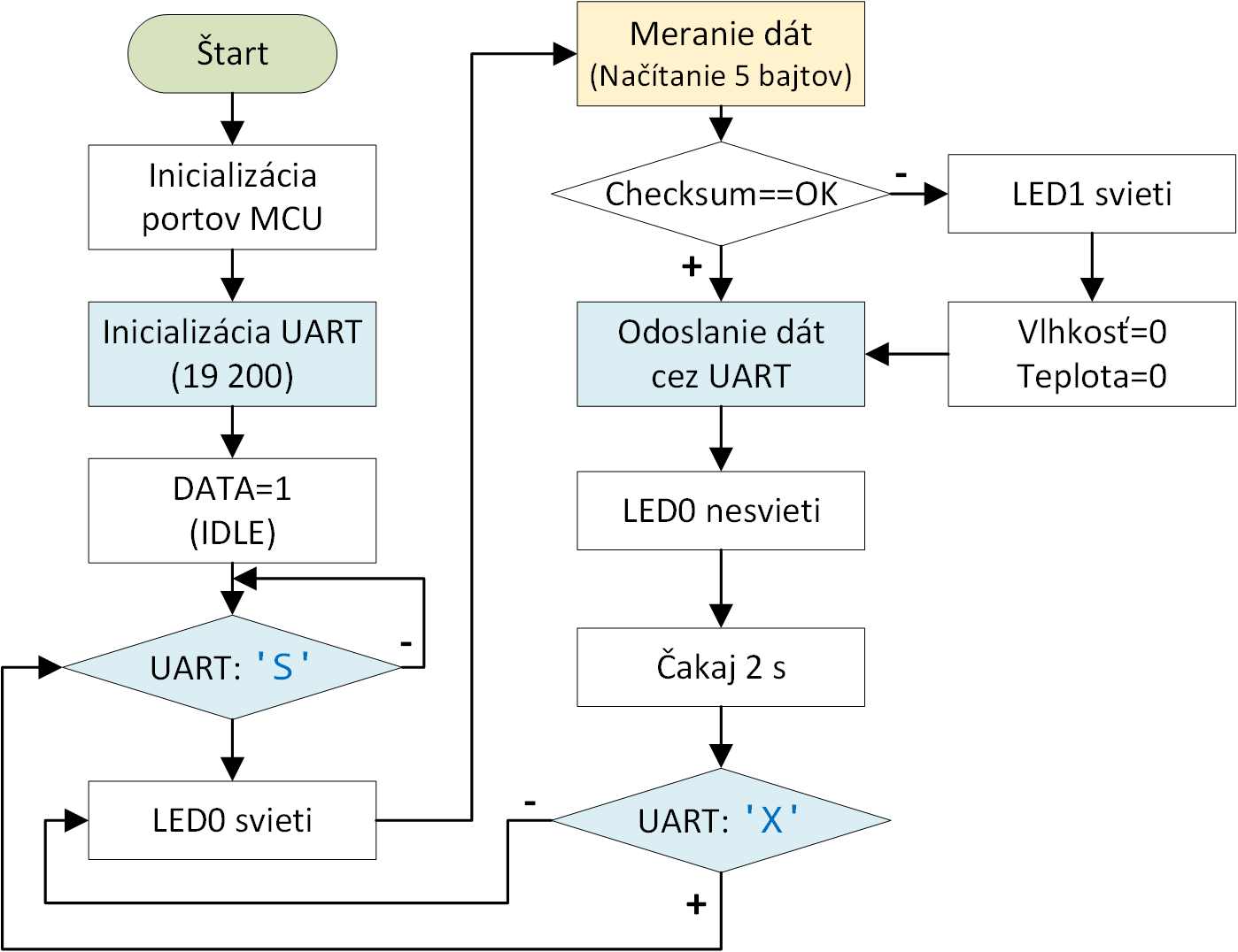
- Structure the program according to the flowchart below:
- Create a graphical user interface application in MATLAB App Designer that displays the current relative humidity in [%] and temperature in [°C] (Fig. 7). The application must include the following UI elements:
- A text field displaying current humidity,
- A text field displaying current temperature,
- Buttons: 'Open Port', 'Start', and 'Stop'.
- Create a detailed flowchart of the MCU code segment illustrating single-wire data acquisition from the DHT22 sensor.
- Evaluate the laboratory exercise. Focus on the following points:
- MCU firmware development and problematic implementation steps,
- MATLAB application development.