


1. Theoretical Introduction
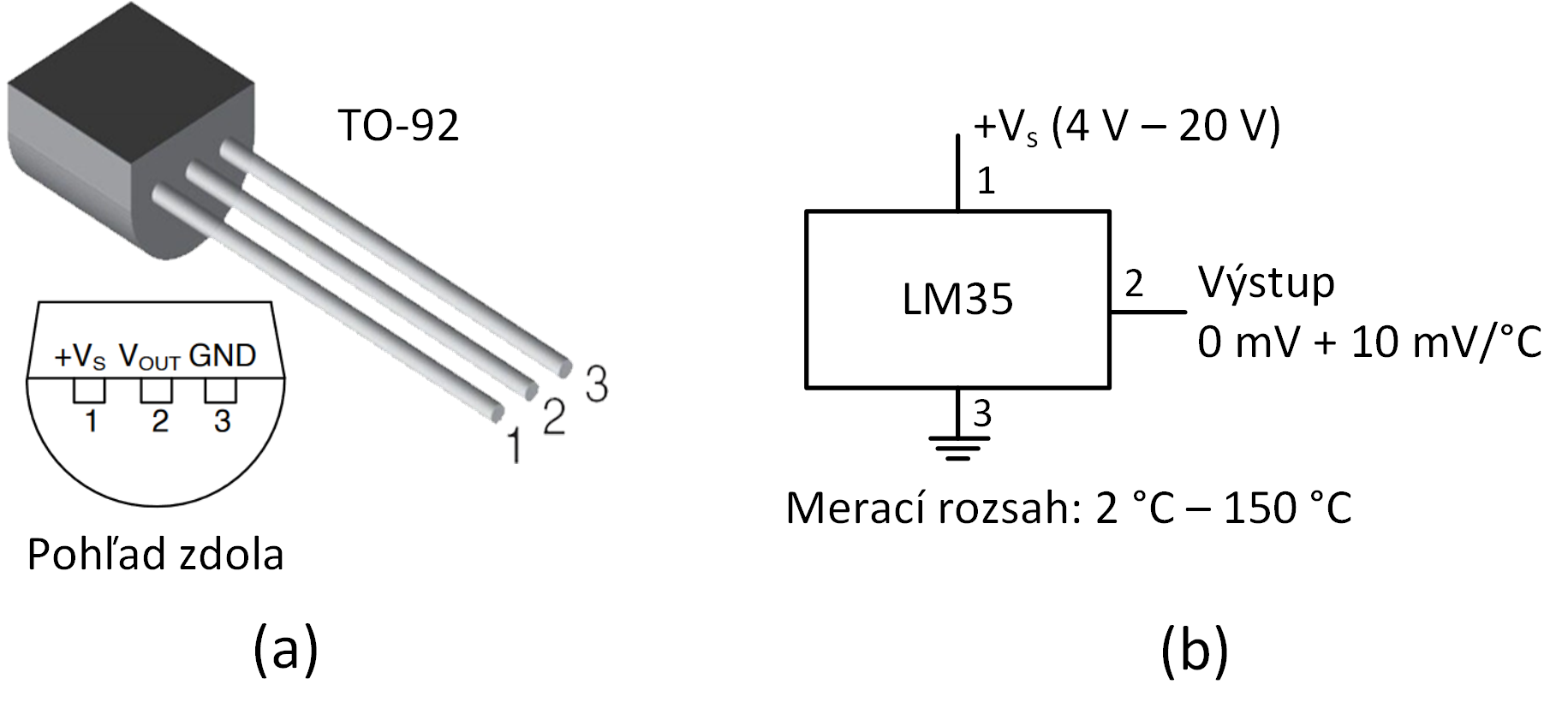
The LM35 integrated circuit is a precision temperature sensor with an electrical output voltage linearly proportional to the Celsius temperature. The LM35 device has an advantage over linear temperature sensors calibrated in Kelvin, as the user is not required to subtract a large constant voltage from the output to obtain convenient Centigrade scaling. The sensor does not require any external calibration to provide typical accuracies of ±0.25 °C at room temperature and ±0.75 °C over a full −55 °C to 150 °C temperature range. Low output impedance (0.1 Ω for 1 mA load), linear output, and precise inherent calibration make interfacing to readout or control circuitry especially easy. The device is used with single power supplies, or with plus and minus supplies. As the LM35 device draws only 60 μA from the supply, it has very low self-heating of less than 0.1 °C in still air. The LM35 sensor is manufactured in various packages—TO-92, TO-220, TO-CAN, and SOIC8. In this laboratory assignment, the TO-92 package is used (Fig. 1a). The basic connection circuit for measuring temperatures from 2 °C to 150 °C is shown in Fig. 1b.

where T is the temperature in °C. From this equation, it follows that simply dividing the measured voltage value in [mV] by 10 yields the temperature directly in degrees Celsius [°C].
Several device types are manufactured within the LM35 family, including the LM35, LM35A, LM35C, and others. The individual models differ primarily in their temperature ranges and accuracy ratings. This laboratory exercise utilizes the LM35DZ sensor, which features a restricted temperature range of 0 °C to 100 °C and a typical accuracy of ±0.6 °C at room temperature.
2. Equipment Used
- Hardware
- Mega Development Board 2 (MDB2)
- LM35DZ analog temperature sensor
- PC
- Software
- MATLAB
- Microchip Studio
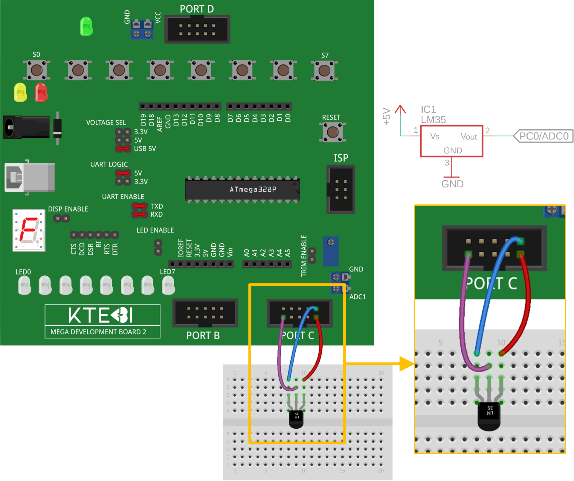
3. Schematic Diagram
4. Assignment Tasks
- Connect the LM35 temperature sensor to the MDB2 development board according to the connection diagram (Fig. 2). Use USB power supply. The jumper positions on the MDB2 are highlighted in red.
- Write an MCU program in C that digitizes the output from the temperature sensor and transmits the digital samples to the PC via UART. Implement the following parameters and functionality in the code:
- Select the internal 1.1 V voltage reference for the ADC,
- Transmit digital samples to the PC every 100 ms,
- Configure the UART communication speed to 19,200 Baud,
- Start sending samples to the PC only after receiving the character 'S', and stop sending after receiving the character 'X'. Use the UART receive interrupt to detect incoming characters.
- In MATLAB App Designer, create an application with a graphical user interface that displays the current temperature in °C and plots its trend over time as shown in Fig. 3. The application must include the following components:
- A plot for rendering the real-time temperature graph over time,
- A label or edit field displaying the current temperature value,
- Pushbuttons: 'Open Port', 'Start', and 'Stop'.

- Create a flowchart of the MCU firmware program.
- Evaluate the outcome of the laboratory exercise. Focus on the following points:
- Writing the MCU firmware, challenging implementation sections,
- Developing the MATLAB companion application.