


Interrupts in AVR Microcontrollers
An interrupt is a hardware mechanism that allows the microcontroller to respond immediately to critical internal or external asynchronous events without requiring continuous status polling within the main application loop. When an interrupt event occurs, the CPU suspends foreground execution of the main program, pushes the return address onto the Stack, and branches to an Interrupt Service Routine (ISR). Once the ISR completes execution, the CPU restores its previous execution context and resumes the main routine seamlessly.
Each interrupt source is mapped to a dedicated address in flash program memory known as an Interrupt Vector. For an interrupt request to be serviced by the CPU, three conditions must be satisfied:
- The triggering hardware event must take place (e.g., an external pin transition, a timer overflow, or a received serial byte), which asserts the corresponding Interrupt Flag.
- The specific interrupt must be unmasked locally in the respective peripheral control register (e.g., bits TOIE0, OCIE0A, or RXCIE0).
- Global interrupts must be enabled by asserting the I bit in the Status Register (SREG) via the sei() instruction. Conversely, interrupts can be disabled globally using the cli() instruction.
External Interrupts
External interrupts can be triggered via the INT0 and INT1 pins, or via any of the PCINT23 – PCINT0 pins. It is important to note that an external interrupt will trigger even if the pins INT0, INT1, PCINT23 – PCINT0 are configured as outputs. External interrupts can be divided into two groups.
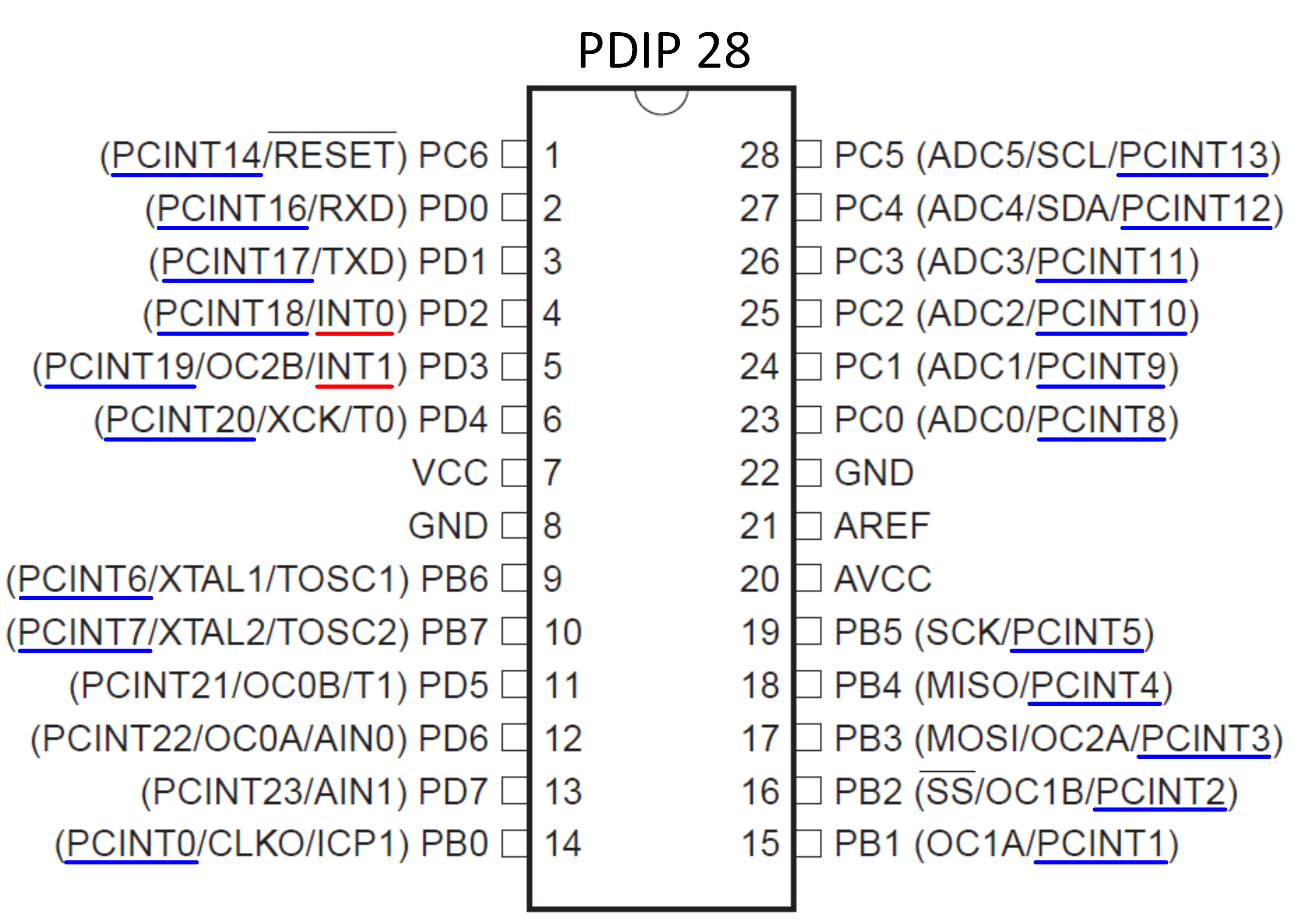 Fig. 1: ATmega328P external interrupt pins (PDIP).
The first group consists of interrupts triggered by the INT0 and INT1 pins. An interrupt can be triggered by a rising edge, falling edge, or low voltage level on the INT0 and INT1 pins. This configuration is carried out using the EICRA register. An interrupt triggered by a rising or falling edge requires the MCU oscillator to be active. This means that edge-triggered interrupts cannot be used to wake the MCU from Power-down mode, where the oscillator is halted to minimize power consumption. Conversely, a low-level interrupt on the INT0 or INT1 pin is detected asynchronously (independent of the MCU clock oscillator). Therefore, low-level interrupts can be used to wake the MCU from Power-down mode.
The second group consists of interrupts referred to as Pin Change Interrupts (PCI). This type of external interrupt is triggered by any logic level transition on the pins designated as PCINT23 – PCINT0 (see Fig. 1). The pins PCINT23 – PCINT0 are organized into three groups:
| Group Name | Pins in Group |
|---|---|
| PCI2 (Pin Change Interrupt 2) | PCINT23 - PCINT16 |
| PCI1 (Pin Change Interrupt 1) | PCINT14 - PCINT8 |
| PCI0 (Pin Change Interrupt 0) | PCINT7 - PCINT0 |
Interrupts for groups PCI2 – PCI0 are enabled via the PCICR register. Subsequently, the individual external interrupt pins within that group are unmasked in registers PCMSK2 – PCMSK0. An example of enabling an external interrupt on pin PCINT13 (PC5) is as follows:
//Pin PCINT13 belongs to group PCI1
PCICR|=(1<<PCIE1); //Enable pin change interrupt for group PCI1
PCMSK1|=(1<<PCINT13); //Enable pin change interrupt on pin PCINT13
sei(); //Global interrupt enable
Important Registers

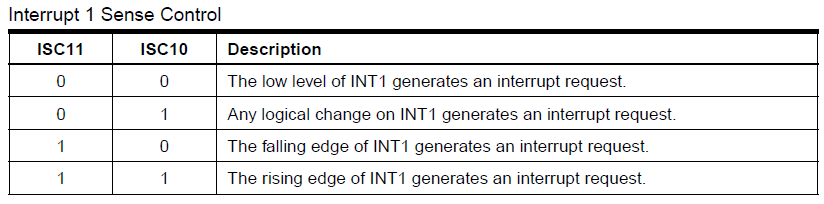
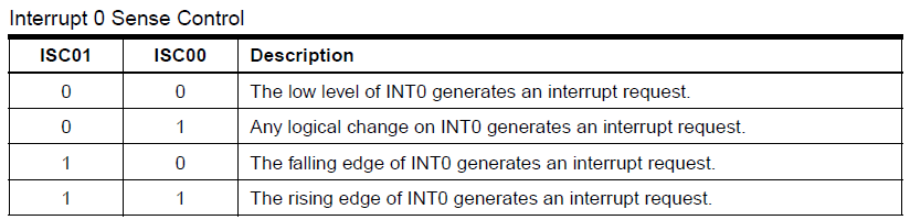


PCICR – Pin Change Interrupt Control Register, used to enable pin change interrupts (PCI) on groups of pins.

- The PCIE2 bit enables interrupts for the PCINT23..16 pin group. Pins PCINT23..16 are individually unmasked in the PCMSK2 register.
- The PCIE1 bit enables interrupts for the PCINT14..8 pin group. Pins PCINT14..8 are individually unmasked in the PCMSK1 register.
- The PCIE0 bit enables interrupts for the PCINT7..0 pin group. Pins PCINT7..0 are individually unmasked in the PCMSK0 register.
- Note: The interrupt will execute only when global interrupts are enabled via sei().
PCIFR – Pin Change Interrupt Flag Register, which provides indication of pending pin change interrupts on a group of pins via interrupt flags.

- A logic state transition on any enabled PCINT23..16 pin will trigger an interrupt request and set the PCIF2 bit to logic one. If global interrupts are enabled (sei()) and the group interrupt is enabled in the PCICR register (PCIE2 = 1), the MCU branches to the corresponding interrupt vector — PCINT2_vect. The PCIF2 bit is cleared automatically when the interrupt routine is executed, or manually by writing a logic one to the bit.
- A logic state transition on any enabled PCINT14..8 pin will trigger an interrupt request and set the PCIF1 bit to logic one. If global interrupts are enabled (sei()) and the group interrupt is enabled in the PCICR register (PCIE1 = 1), the MCU branches to the corresponding interrupt vector — PCINT1_vect. The PCIF1 bit is cleared automatically when the interrupt routine is executed, or manually by writing a logic one to the bit.
- A logic state transition on any enabled PCINT7..0 pin will trigger an interrupt request and set the PCIF0 bit to logic one. If global interrupts are enabled (sei()) and the group interrupt is enabled in the PCICR register (PCIE0 = 1), the MCU branches to the corresponding interrupt vector — PCINT0_vect. The PCIF0 bit is cleared automatically when the interrupt routine is executed, or manually by writing a logic one to the bit.
PCMSK2 – Pin Change Mask Register 2, used to selectively enable the pin change interrupt (PCI) on individual MCU pins within the PCINT23..16 group.

- Bits PCINT23..16 determine whether the pin change interrupt (PCI) is enabled on each respective MCU pin.
PCMSK1 – Pin Change Mask Register 1, used to selectively enable the pin change interrupt (PCI) on individual MCU pins within the PCINT14..8 group.

- Bits PCINT14..8 determine whether the pin change interrupt (PCI) is enabled on each respective MCU pin.
PCMSK0 – Pin Change Mask Register 0, used to selectively enable the pin change interrupt (PCI) on individual MCU pins within the PCINT7..0 group.

- Bits PCINT7..0 determine whether the pin change interrupt (PCI) is enabled on each respective MCU pin.
Timer Interrupts
Hardware timers operate autonomously in the background, allowing them to fire periodic interrupts at deterministic intervals without CPU intervention. For Timer0, two primary interrupt types are commonly implemented:
- Timer Overflow Interrupt: Asserted when the counter register TCNT0 rolls over from its maximum capacity 255 back to 0. This event sets the TOV0 flag in the TIFR0 register. It is unmasked by setting the TOIE0 bit in TIMSK0 and vectors to TIMER0_OVF_vect.
- Output Compare Match Interrupt: Asserted when the counter register TCNT0 matches the preset reference threshold in OCR0A (or OCR0B). This event asserts the OCF0A flag in TIFR0. It is enabled via the OCIE0A bit in TIMSK0 and handled within the TIMER0_COMPA_vect routine. When combined with CTC mode, it provides an ideal architecture for executing cyclic foreground tasks with high timing accuracy.
Combining Timer and External Interrupts
AVR microcontrollers support multiple active interrupt sources concurrently. If multiple interrupt requests occur simultaneously, they are serviced according to a fixed hardware priority defined by the vector table layout (with reset and external pin interrupts having higher priority than peripheral timers). Upon entering an ISR, the CPU clears the global interrupt flag (bit I in SREG), preventing nested interrupts by default. Global interrupts are restored upon execution of the return-from-interrupt instruction (RETI). This enables designs where a background timer maintains base system timing while external pin interrupts respond asynchronously to asynchronous external inputs such as user button presses.
USART Interrupts
Serial communication operates at significantly lower data rates than the core CPU clock. Blocking the processor while polling for transmission completion or waiting for incoming characters wastefully consumes compute resources. The USART peripheral therefore provides dedicated interrupt vectors for non-blocking, interrupt-driven serial I/O:
- Receive Complete Interrupt (USART Rx Complete): Triggered whenever new unread data is shifted into the receive buffer, setting the RXC0 flag in register UCSR0A. It is enabled by asserting the RXCIE0 bit in UCSR0B and handled inside the USART_RX_vect ISR. Reading the UDR0 data register within the ISR automatically clears the interrupt flag.
- Data Register Empty Interrupt: Triggered when the UDRE0 flag is set, indicating that the transmit buffer UDR0 is ready to accept a new byte for transmission (vectored to USART_UDRE_vect, enabled via UDRIE0).
- Transmit Complete Interrupt (USART Tx Complete): Triggered after all frame bits (including stop bits) have been completely shifted out of the transmitter shift register (vectored to USART_TX_vect, enabled via TXCIE0).
Example 1 (External Interrupt)
This example demonstrates using a pushbutton as a source of an external interrupt. The program is designed such that LED0 (connected to PORTB0) blinks initially. Pressing pushbutton S2 (connected to PIND2 / INT0) triggers the interrupt, switching the blinking LED so that LED1 starts blinking. Each subsequent press of the button advances the blinking pattern to the next LED. Once the final LED7 is blinking, pressing the button wraps around to LED0 again.
#define F_CPU 8000000UL
#include <avr/io.h>
#include <avr/interrupt.h>//nutne pridat kniznicu preruseni
#include <util/delay.h>
uint8_t LED=0;//poradie LED,napr. LED=3 rozsvieti sa LED3 (PORTB3)
ISR(INT0_vect)//vektor/obsluha externeho prerusenia
{
//prerusenie sa spusti pri zostupnej hrane (prechod z log.1 na log.0) na INT0
cli();//globalne zakazanie preruseni (aby sa nespustilo znova prerusenie)
PORTB=0;//zhasne vsetky LED
LED++;//zmeni LED,ktora bude blikat
if (LED>=8)//LED c.8 nie je,musi byt zmenene na LED0
LED=0;//po LED7 zacne blikat LED0
_delay_ms(200);//zdrzi program 200 ms,preckanie zakmitov tlacidla
//vymaze priznak prerusenia (interrupt flag) zapisom log.1,
//inak by hned voslo do prerusenia kvoli zakmitom tlacidla
EIFR|=(1<<INTF0);
sei();//opatovne povolenie globalnych preruseni
//po dokonceni programu v preruseni,sa program vrati tam kde predtym skoncil
}
int main(void)
{
DDRB=255;//PORTB ako vystupny (pripojene LED)
PORTB=0;//vsetky LED zhasnute
DDRD=0;//PORTD ako vstupny (pripojene tlacidla)
PORTD=255;//zapnutie pull-up rezistorov na PORTD
//nastavenie prerusenia od INT0
EICRA|=(1<<ISC01);//zostupna hrana na pine PIND2 (INT0) spusti prerusenie
EIMSK|=(1<<INT0);//povolenie prerusenia od INT0
uint8_t LED_svieti = 0;
sei();//globalne povolenie preruseni
while (1)
{
if (LED_svieti) //ak LED svieti
{
PORTB&=~(1<<LED);//zhasne LED
LED_svieti=0;
}
else //ak LED nesvieti
{
PORTB|=(1<<LED); //zasvieti LED
LED_svieti=1;
}
_delay_ms(200);//pocka 0.2s
}
}
Example 2 (Timer Interrupt)
This example is very similar to Example 4 presented in the Timers section. The objective is to blink LED0 at the same frequency as in the previous example. However, the code segment responsible for blinking is not placed inside the infinite while(1) loop in main(), but is executed within the timer interrupt service routine. Timers were covered in detail in Lesson 2. In this example, the interrupt is triggered every 200 µs, executing the required number of cycles (1,000 times) until the desired interval (1,000 × 200 µs = 200 ms) for turning the LED on/off is reached.
#define F_CPU 8000000UL
#include <avr/io.h>
#include <avr/interrupt.h>//nutne pridat kniznicu preruseni
/* globalne premenne */
uint8_t LED = 0;//poradie LED,napr. LED=3 rozsvieti sa LED3 (PORTB3)
uint8_t LED_svieti = 0;
uint16_t pocitadlo = 0;
ISR(TIMER0_COMPA_vect) //obsluha prerusenia casovaca0
{
//prerusenie sa spusta kazdych 200us
pocitadlo++;
if (pocitadlo == 1000) //ubehlo 200ms = 1000 x 200us
{
pocitadlo=0;
if (LED_svieti) //ak LED svieti
{
PORTB&=~(1<<LED);//zhasne LED
LED_svieti=0;
}
else //ak LED nesvieti
{
PORTB|=(1<<LED); //zasvieti LED
LED_svieti=1;
}
}
}
int main(void)
{
DDRB=255;//PORTB ako vystupny (pripojene LED)
PORTB=0;//vsetky LED zhasnute
/* nastavenie casovaca 0 */
TCCR0B|=(1<<CS01);//zapne casovac, predelicka 8 -> frekvencia casovaca f=1 MHz (T=1 us)
OCR0A=200;//nastavenie registra zhody (200xT=200 us)
TCCR0A|=(1<<WGM01);//automaticke nulovanie casovaca0 (TCNT0) pri dosiahnuti hodnoty v OCR0A
TIMSK0=(1<<OCIE0A); //povolenie prerusenia casovaca0
/* * * * * * * * * * * * */
sei();//globalne povolenie preruseni
while (1)
{
//blikanie LED sa realizuje v preruseni casovaca
}
}
Example 3 (Timer Interrupt + External Interrupt)
This example combines the functionality of Example 1 and Example 2. LED blinking is handled inside the timer interrupt service routine, while cycling through the active blinking LED is handled by pushbutton S2 inside the external interrupt service routine.
#define F_CPU 8000000UL
#include <avr/io.h>
#include <avr/interrupt.h>//nutne pridat kniznicu preruseni
#include <util/delay.h>
/* globalne premenne */
uint8_t LED = 0;//poradie LED,napr. LED=3 rozsvieti sa LED3 (PORTB3)
uint8_t LED_svieti = 0;
uint16_t pocitadlo = 0;
ISR(TIMER0_COMPA_vect) //obsluha prerusenia casovaca0
{
//prerusenie sa spusta kazdych 200us
pocitadlo++;
if (pocitadlo == 1000) //ubehlo 200ms = 1000 x 200us
{
pocitadlo=0;
if (LED_svieti) //ak LED svieti
{
PORTB&=~(1<<LED);//zhasne LED
LED_svieti=0;
}
else //ak LED nesvieti
{
PORTB|=(1<<LED); //zasvieti LED
LED_svieti=1;
}
}
}
ISR(INT0_vect)//vektor/obsluha externeho prerusenia
{
//prerusenie sa spusti pri zostupnej hrane (prechod z log.1 na log.0) na INT0
cli();//globalne zakazanie preruseni (aby sa nespustilo znova prerusenie)
PORTB=0;//zhasne vsetky LED
LED++;//zmeni LED,ktora bude blikat
if (LED>=8)//LED c.8 nie je,musi byt zmenene na LED0
LED=0;//po LED7 zacne blikat LED0
_delay_ms(200);//zdrzi program 200 ms,preckanie zakmitov tlacidla
//vymaze priznak prerusenia (interrupt flag) zapisom log.1,
//inak by hned voslo do prerusenia kvoli zakmitom tlacidla
EIFR|=(1<<INTF0);
sei();//opatovne povolenie globalnych preruseni
//po dokonceni programu v preruseni,sa program vrati tam kde predtym skoncil
}
int main(void)
{
DDRB=255;//PORTB ako vystupny (pripojene LED)
PORTB=0;//vsetky LED zhasnute
/* nastavenie casovaca 0 */
TCCR0B|=(1<<CS01);//zapne casovac, predelicka 8 -> frekvencia casovaca f=1 MHz (T=1 us)
OCR0A=200;//nastavenie registra zhody (200xT=200 us)
TCCR0A|=(1<<WGM01);//automaticke nulovanie casovaca0 (TCNT0) pri dosiahnuti hodnoty v OCR0A
TIMSK0=(1<<OCIE0A); //povolenie prerusenia casovaca0
/* * * * * * * * * * * * */
DDRD=0;//PORTD ako vstupny (pripojene tlacidla)
PORTD=255;//zapnutie pull-up rezistorov na PORTD
//nastavenie prerusenia od INT0
EICRA|=(1<<ISC01);//zostupna hrana na pine PIND2 (INT0) spusti prerusenie
EIMSK|=(1<<INT0);//povolenie prerusenia od INT0
sei();//globalne povolenie preruseni
while (1)
{
//blikanie LED sa realizuje v preruseni casovaca
}
}
Example 4 (USART Interrupt)
This example demonstrates another interrupt type: an interrupt triggered upon receiving a byte over USART. The USART interface was described in detail in Lesson 3. Inside main(), an infinite while(1) loop blinks LED0. Receiving a byte via the USART interface triggers the interrupt service routine without interrupting the blinking routine of LED0. The interrupt routine transmits the received byte back to the PC as an echo. For example, if the character 'A' is sent from the PC, the MCU replies with the same character, resulting in the PC receiving 'A'.
#define F_CPU 8000000UL
#include <avr/io.h>
#include <avr/interrupt.h>//nutne pridat kniznicu preruseni
#include <util/delay.h>
uint8_t LED=0;//poradie LED,napr. LED=3 rozsvieti sa LED3 (PORTB3)
void USART_Init()
{
// Nastavenie USART - 8 datovych bitov,jeden stop bit,ziadna parita
UBRR0=25; //nastavena rychlost 19200 Baud (z datasheetu) pri f_MCU=8MHz
UCSR0B|=(1<<TXEN0)|(1<<RXEN0); //zapnutie vysielaca a prijimaca
}
ISR(USART_RX_vect)//obsluha prerusenie od USART pri prijati bajtu
{
cli();//globalne zakazanie preruseni
while ( !(UCSR0A & (1<<RXC0)) ) ;//caka na dokoncenie prijatia
uint8_t prijatyBajt=UDR0;
//odoslanie toho isteho bajtu nazad
while ( !( UCSR0A & (1<<UDRE0)) ) ; //pocka na vyprazdnenie buffera
UDR0 = prijatyBajt; //odoslanie bajtu cez USART
sei();//opatovne povolenie globalnych preruseni
}
int main(void)
{
DDRB=255;//PORTB ako vystupny (pripojene LED)
PORTB=0;//vsetky LED zhasnute
USART_Init();//inicializacia USART
//povolenie prerusenia od USART pri prijati bajtu (USART Recieve Complete interrupt)
UCSR0B |= (1 << RXCIE0);
uint8_t LED_svieti = 0;
sei();//globalne povolenie preruseni
while (1)
{
if (LED_svieti) //ak LED svieti
{
PORTB&=~(1<<LED);//zhasne LED
LED_svieti=0;
}
else //ak LED nesvieti
{
PORTB|=(1<<LED); //zasvieti LED
LED_svieti=1;
}
_delay_ms(200);//pocka 0.2s
}
}