


Serial communication is one of the most widespread data transfer methods. Individual data elements are transmitted sequentially over a single transmission line over time. When receiving data, the receiver must be synchronized with the transmitter. Therefore, the receiver must identify the beginning and the end of signal state transitions—the starts and ends of data blocks, known as a data frame. Based on this information, the receiver determines the precise sampling instant to evaluate the data frame.
The synchronous/asynchronous serial interface USART (Universal Synchronous/Asynchronous Receiver and Transmitter) is a hardware peripheral used for serial communication in asynchronous mode (RS-232, RS-422, ...) or synchronous mode (SPI). The asynchronous mode is commonly referred to as UART (Universal Asynchronous Receiver/Transmitter). The USART transmits data on the pin designated as TX or TXD (transmit) and receives data on the pin RX or RXD (receive). The idle signal state is logic 1 (when neither transmission nor reception is taking place). Transmission begins with a transition of the signal state to logic 0 for the duration of one bit (the start bit). Next, the least significant bit (LSB) is sent first, followed by the most significant bit (MSB), which is then followed by one or two stop bits that return to logic 1. After the final stop bit has been transmitted, transfer of the next byte can begin. The number of data bits can range from 5 to 9. The ninth data bit can serve as a parity bit.
 Data frame format. St - Start bit (always low level); (0 - 8) - data bits; P - parity bit; Sp - Stop bit (always high level); IDLE - no data transmission. Bits shown in [ ] are optional and need not be included in the frame.
Important Registers
This section describes several registers associated with the USART interface that are used in the examples below. The register names use the index n. The index n is used because certain AVR microcontrollers feature multiple USART interfaces (e.g., ATmega328PB has 2 USART interfaces [USART0, USART1], ATmega2560 has 4 USART interfaces [USART0 - USART3]). The ATmega328P MCU features only one USART interface, so the index n should be replaced with the number 0 in register names (e.g., UDR0, UCSR0A, ...).
UDR0 – Transmit and Receive Data Register (8-bit). Writing a byte to the UDR0 register initiates transmission of the byte over USART. Reading the UDR0 register retrieves the byte received via the USART interface. When receiving data continuously, the UDR0 register must be read out promptly to avoid overwriting the register before the received byte can be processed.

UCSR0A – Control and Status Register A, used to verify byte reception/transmission and to enable double transmission speed mode.

- The RXC0 bit is used to check for received data. Bit RXC0 is set to logic 1 when unread data is present in the receive buffer, and it is cleared when the receive buffer is empty (e.g., contains no unread data).
- The TXC0 bit is set to logic 1 when the entire frame (all bits) has been shifted out and no new data is present in the transmit buffer. Bit TXC0 is cleared automatically when the transmit complete interrupt vector is executed, or manually by writing a logic 1 to the bit position.
- The UDRE0 bit indicates whether the UDR0 register is ready to accept new data. If bit UDRE0 = 1, the transmit buffer UDR0 is empty and new data can be written to it.
- The U2X0 bit is used to enable double transmission speed. If bit U2X0 is set to logic 1, the baud rate prescaler divisor is reduced from 16 to 8, effectively doubling the transfer rate. This setting is functional only in asynchronous mode.
UCSR0B – Control and Status Register B, used to enable/disable the receiver and transmitter, as well as to enable interrupts on data reception and transmission.

- If bit RXCIE0 = 1, the interrupt for the RXC0 flag is enabled (i.e., upon receiving a byte via USART). For this interrupt to execute, global interrupts must be enabled via sei().
- If bit TXCIE0 = 1, the interrupt for the TXC0 flag is enabled (i.e., upon completing transmission of a byte via USART). For this interrupt to execute, global interrupts must be enabled via sei().
- If bit RXEN0 = 1, the receiver is enabled (data reception via USART). Enabling the receiver overrides normal port operation for pin RXD (PD0).
- If bit TXEN0 = 1, the transmitter is enabled (data transmission via USART). Enabling the transmitter overrides normal port operation for pin TXD (PD1).
UCSR0C – Control and Status Register C, used to configure the operating mode (synchronous/asynchronous), parity, number of stop bits, and character size (data bit count) for USART communication.

- Bits UMSEL01 and UMSEL00 are used to select synchronous or asynchronous mode.

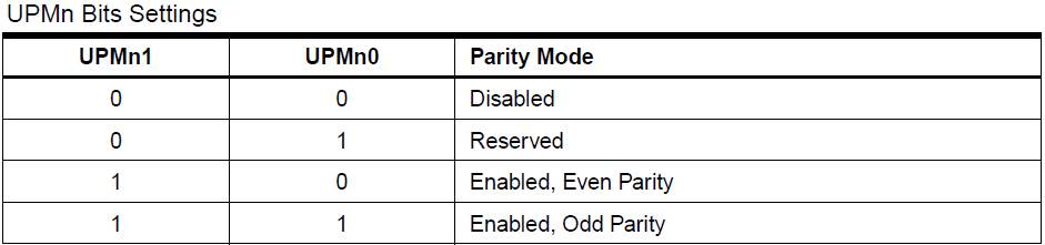
- Bits UPM01 and UPM00 are used to configure parity mode.
- Bit USBS0 is used to set the number of stop bits.

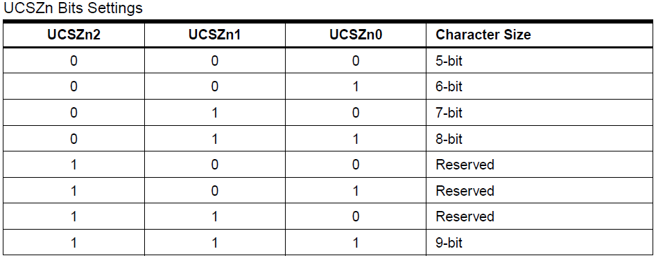
- Bits UCSZ02, UCSZ01, and UCSZ00 are used to configure the character size (number of data bits). Note that bit UCSZ02 is located in the UCSR0B register.
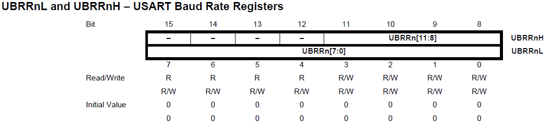
The transmission speed (Baud Rate) can be configured by writing the appropriate value to the 12-bit register UBRR0.
The following table provides the formulas for calculating the UBRR0 register value according to the desired BAUD rate.
Table 1: Calculating the UBRR0 register value according to the required Baud Rate.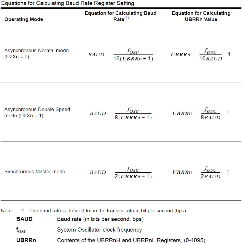
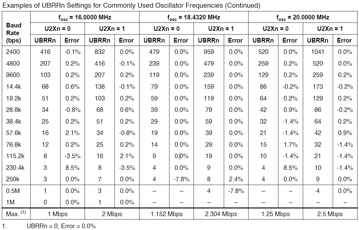
Baud rates over serial links are standardized; therefore, the ATmega328P datasheet provides tables listing the required UBRR0 register values for selected baud rates and given MCU clock frequencies (fOSC). Depending on the MCU clock frequency (fOSC) and using the formulas in Table 1, it is not always possible to configure every arbitrary Baud Rate listed in Table 2 and Table 3 without error. The tables include an Error column indicating the percentage error between the configured (calculated) baud rate and the requested baud rate. As seen from the table, for fOSC = 8 MHz, only a few baud rates achieve an error of 0.0%. For reliable communication, the transmission error should be below 0.5%. This means that even with fOSC = 8 MHz, settings yielding a 0.2% error in Table 2 can be reliably used. A different MCU clock frequency (e.g., fOSC = 11.0592 MHz) allows selecting from a wider range of standard baud rates with an error of 0.0%.
Table 2: Baud rate settings based on MCU clock frequency (8 MHz - 14.7458 MHz).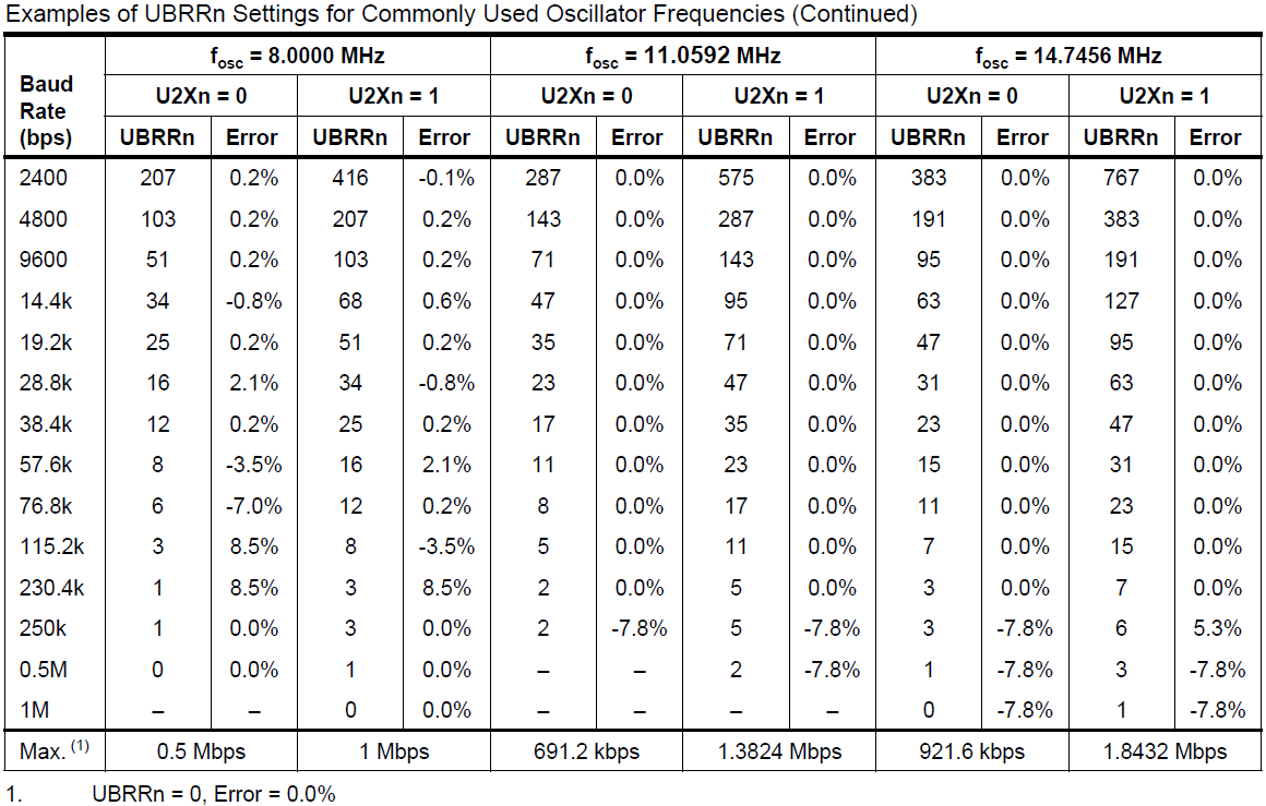 Table 3: Baud rate settings based on MCU clock frequency (16 MHz - 20 MHz).
USART communication takes place between at least two devices. It is most commonly used for communication between a device (MCU) and a personal computer, or between an MCU and peripheral circuits. To verify the implemented USART communication, a PC will be used. Modern computers no longer feature a 9-pin RS-232 serial COM port. This port has been replaced by USB. For this reason, a USB-to-UART converter bridge, such as the FT232RL utilized on the Mega Development Board 1 and Mega Development Board 2 or FT231XS utilized on the Angry Bear Board, must be placed between the MCU and the PC. To test the examples provided below, a PC companion application was created, which you can download here.
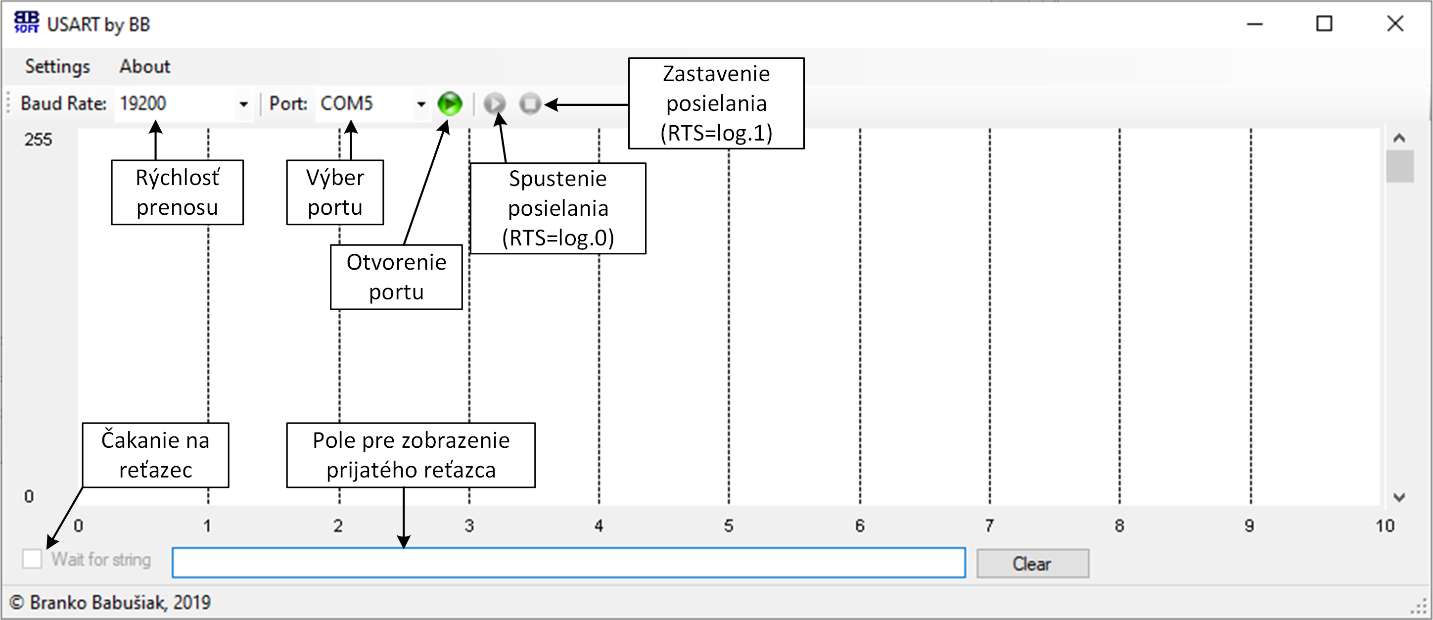 Preview of the USART PC application with control button descriptions.
Example 1
In the following example, the USART interface is initialized with the following parameters:
- Asynchronous mode
- 8 data bits
- 1 stop bit
- No parity bit
- Baud rate of 19,200 Baud
Using the USART interface, a text string containing a name is sent to the computer when pushbutton S0, connected to pin PINB0, is pressed. You can verify code functionality using the application referenced above.
#define F_CPU 8000000UL
#include <avr/io.h>
#include <util/delay.h>
int main(void)
{
/***** ***** ***** ***** ***** *****
* Nasledujuca cast kodu je nadbytocna, pretoze danemu nastaveniu seriovej
* komunikacie vyhovuje prednastavena (default) hodnota registrov
***** ***** ***** ***** ***** *****/
UCSR0C&=~(1<<USBS0); //nastavenie jedneho stop bitu
UCSR0C&=~((1<<UPM01)|(1<<UPM00)); //nastavenie ziadnej parity
UCSR0C|=(1<<UCSZ01)|(1<<UCSZ00); //nastavenie 8 datovych bitov
UCSR0B&=~(1<<UCSZ02); //nastavenie 8 datovych bitov
/* Koniec nadbytocnej casti kodu
***** ***** ***** ***** ***** *****/
UBRR0=25; //nastavena rychlost 19200 Baud (z datasheetu) pri f_MCU=8MHz
UCSR0B|=(1<<TXEN0); //zapnutie vysielaca
DDRD=0; //PORTD ako vstup
PORTD=255; //pull-up na PORTD
char meno[15]="Ferko Mrkvicka"; //+1 znak navyse kvoli koncu retazca \0
while (1)
{
if (! (PIND&(1<<PIND0))) //ci bolo stlacene tlacidlo pripojene k pinu PIND0
{
for (unsigned char k=0;k<15;k++) //odosielanie retazca po jednotlivych znakoch
{
while ((UCSR0A&(1<<UDRE0))==0) ; //kontrola vyprazdnenia buffera UDR0
UDR0=meno[k]; //odoslanie znaku
}
//cakanie 1 s (10 x 100ms),aby nedoslo k
//viacnasobnej registracii stlacenia tlacidla
for (uint8_t k=0;k<10;k++)
_delay_ms(100);
}
}
}
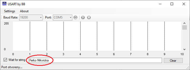 Received string in the USART application (the "Wait for string" checkbox must be enabled).
Example 2
The following example performs the same function as Example 1, with the difference that USART initialization and character transmission routines are encapsulated within functions. Organizing functional code blocks into dedicated functions substantially improves code readability and modularity.
#define F_CPU 8000000UL
#include <avr/io.h>
#include <util/delay.h>
void USART_Init()
{
// Nastavenie USART-8 datovych bitov,jeden stop bit,ziadna parita
// - uvedene parametre su vychodiskove hodnoty registrov,
// preto nie je potrebne nastavovat
UBRR0=25; //nastavena rychlost 19200 Baud (z datasheetu) pri f_MCU=8MHz
UCSR0B|=(1<<TXEN0); //zapnutie vysielaca
}
void USART_send(unsigned char bajt)
{
while ( !( UCSR0A & (1<<UDRE0)) ) ; //pocka na vyprazdnenie buffera
UDR0 = bajt; //odoslanie bajtu cez USART
}
int main(void)
{
USART_Init(); //inicializacia USART
DDRD=0; //PORTD ako vstup
PORTD=255; //pull-up na PORTD
char meno[15]="Ferko Mrkvicka"; //+1 znak navyse kvoli koncu retazca \0
while (1)
{
if (! (PIND&(1<<PIND0))) //ci bolo stlacene tlacidlo pripojene k pinu PIND0
{
for (unsigned char k=0;k<15;k++) //odosielanie retazca po jednotlivych znakoch
{
USART_send(meno[k]);
}
//cakanie 1 s (10 x 100ms),aby nedoslo k
//viacnasobnej registracii stlacenia tlacidla
for (uint8_t k=0;k<10;k++)
_delay_ms(100);
}
}
}
Example 3
This example demonstrates transmitting a sawtooth waveform to the PC. The sawtooth signal spans values from 0 to 255, and individual data points are transmitted at a rate of 250 Hz, meaning a sample is sent every 4 ms (1/250). The MCU monitors the state of the RTS control line, which can be toggled from the PC. If the RTS line state is logic 0, individual sawtooth values are transmitted. Conversely, when the RTS line is logic 1, transmission pauses.
#define F_CPU 8000000UL
#include <avr/io.h>
#include <util/delay.h>
void USART_Init()
{
// Nastavenie USART-8 datovych bitov,jeden stop bit,ziadna parita
// - uvedene parametre su vychodiskove hodnoty registrov,
// preto nie je potrebne nastavovat
UBRR0=25; //nastavena rychlost 19200 Baud (z datasheetu) pri f_MCU=8MHz
UCSR0B|=(1<<TXEN0); //zapnutie vysielaca
}
void USART_send(unsigned char bajt)
{
while ( !( UCSR0A & (1<<UDRE0)) ) ; //pocka na vyprazdnenie buffera
UDR0 = bajt; //odoslanie bajtu cez USART
}
int main(void)
{
USART_Init(); //inicializacia USART
DDRD=0; //PORTD ako vstup
PORTD=255; //pull-up na PORTD
PORTD&=~(1<<PIND2); //vypnutie pull-up na PIND2 (RTS)
uint8_t cislo=0;
while (1)
{
if (! (PIND&(1<<PIND2))) //ci je stav linky RTS = log.0
{
USART_send(cislo);
cislo++; //inkrementacia hodnoty premennej cislo
_delay_ms(4); //odosielanie s frekvenciou 250 Hz (1/4ms = 250 Hz)
}
}
}
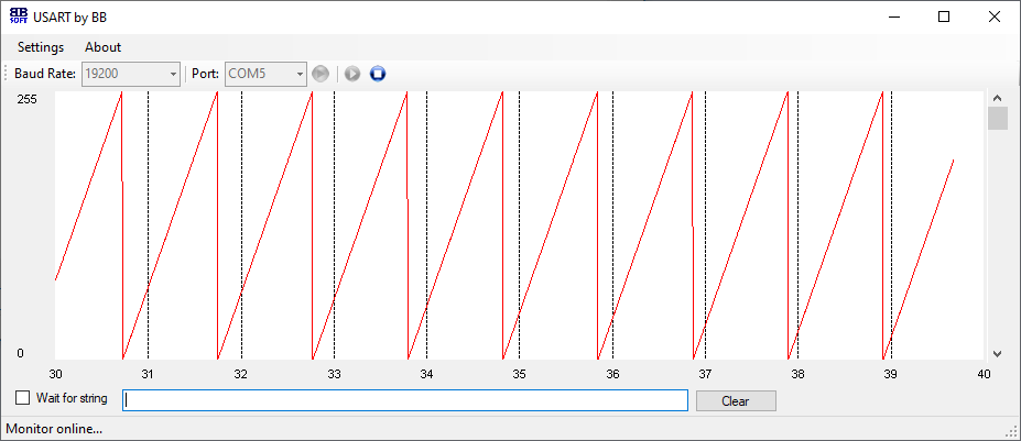 Received sawtooth signal visualized in the USART application.
Downloads
USART Application