


Timers and Counters in AVR Microcontrollers
Timers/Counters are among the most essential peripheral modules of any microcontroller. Their primary purpose is to autonomously measure precise time intervals, count external events (pulses), or generate pulse-width modulated (PWM) signals without placing computational overhead on the main CPU core.
At the core of every timer module lies a hardware counter (data register) that increments by one with each arriving clock tick. This clock signal can either be derived from the microcontroller's internal system oscillator (operating in timer mode) or fed from an external pin (operating in counter mode). To scale down high clock frequencies, a programmable prescaler is utilized. The prescaler divides the system clock frequency by a fixed factor (e.g., 8, 64, 256, 1024), enabling the hardware to measure significantly longer time spans before register overflow occurs.
The ATmega328P microcontroller includes three independent timer peripherals:
- Timer0 – 8-bit Timer/Counter with PWM channels and Output Compare registers,
- Timer1 – 16-bit Timer/Counter offering high resolution and an Input Capture unit,
- Timer2 – 8-bit Timer/Counter featuring asynchronous clocking from an external crystal (ideal for Real-Time Clock – RTC implementations).
This lesson focuses on the 8-bit Timer0. Employing dedicated hardware timers instead of blocking software loops (such as _delay_ms()) is fundamental in embedded software development: the timer operates autonomously in the background, freeing CPU cycles for other tasks and enabling strictly deterministic, interrupt-driven real-time execution.
Important Registers
This section describes several registers and their bits related to the configuration of Timer0, which are used in the examples below.
TCCR0A – This register is primarily used to select the mode of the 8-bit timer Timer0.

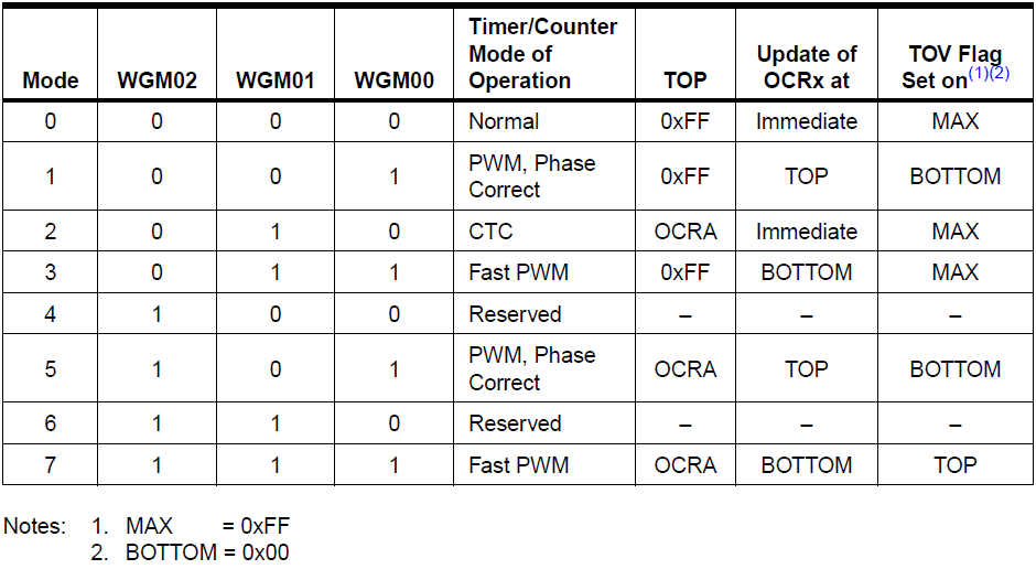
- The timer mode selection is controlled by bits WGM02, WGM01, and WGM00. Note: The WGM02 bit is located in the TCCR0B register! The mode configuration is carried out according to the table below. Only Mode 2 will be described in greater detail, as this mode is frequently used and is also featured in Example 4. This mode is abbreviated as CTC (Clear Timer on Compare Match), meaning that the timer counts up to the value stored in the OCR0A register. Upon reaching this value, the timer value (register TCNT0) is automatically cleared to zero, and the timer resumes incrementing.
TCCR0B – This register is primarily used to select the clock frequency (prescaler) of the 8-bit timer Timer0.

- The WGM02 bit is used when selecting the operating mode of Timer0. The mode configuration is detailed in the description of the TCCR0A register.
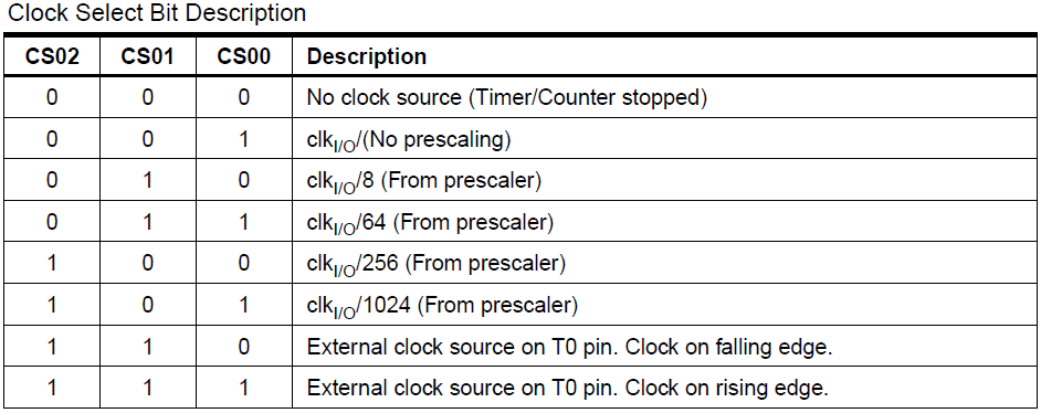
- The CS02, CS01, and CS00 bits are used to set the frequency (timer period). The timer frequency setting depends on the MCU clock frequency. The following table shows the frequency settings for Timer0. If any of the bits CS02, CS01, or CS00 are set to logic one (except for the first row in the table), the timer will start automatically.
TCNT0 – An 8-bit register that stores the current value of the 8-bit timer Timer0. The register supports both read and write access. Writing to the TCNT0 register blocks (clears) the Compare Match on the subsequent timer clock cycle. Modifying the value of TCNT0 while the timer is running may cause a Compare Match between TCNT0 and OCR0A to be missed.

OCR0A – An 8-bit register containing an 8-bit value that is continuously compared against the timer value in TCNT0. A match between the registers TCNT0 and OCR0A can trigger an interrupt or generate an output signal on pin OC0A, depending on the timer mode configuration.

TIMSK0 – An 8-bit register used to enable/disable specific types of timer-related interrupts. The OCIE0B, OCIE0A, and TOIE0 bits serve to enable/disable these specific interrupts.

- If logic one is written to the OCIE0B bit and interrupts are globally enabled (sei()), the Timer/Counter Compare Match B interrupt is enabled. The interrupt is triggered when the OCF0B bit is set in the TIFR0 register.
- If logic one is written to the OCIE0A bit and interrupts are globally enabled (sei()), the Timer/Counter Compare Match A interrupt is enabled. The interrupt is triggered when the OCF0A bit is set in the TIFR0 register.
- If logic one is written to the TOIE0 bit and interrupts are globally enabled (sei()), the timer overflow interrupt is enabled. The interrupt is triggered when the TOV0 bit is set in the TIFR0 register.
TIFR0 – An 8-bit register indicating whether a specific interrupt event has occurred. Interrupt flags are represented by the bits OCF0B, OCF0A, and TOV0.

- If the OCF0B bit contains logic one, a Compare Match has occurred between the timer value and the value stored in the OCR0B register. The OCF0B bit is automatically cleared when the corresponding interrupt vector is executed. Alternatively, the OCF0B bit can be cleared manually by writing a logic one to it. If the OCF0B bit is set and the OCIE0B bit is also set, a Timer/Counter Compare Match Interrupt will be executed.
- If the OCF0A bit contains logic one, a Compare Match has occurred between the timer value and the value stored in the OCR0A register. The OCF0A bit is automatically cleared when the corresponding interrupt vector is executed. Alternatively, the OCF0A bit can be cleared manually by writing a logic one to it. If the OCF0A bit is set and the OCIE0A bit is also set, a Timer/Counter Compare Match Interrupt will be executed.
- The TOV0 bit is set to one when a timer overflow occurs. The TOV0 bit is automatically cleared when the corresponding interrupt vector is executed. Alternatively, the TOV0 bit can be cleared manually by writing a logic one to it. If the TOV0 bit is set and the TOIE0 bit is also set, a Timer/Counter0 Overflow Interrupt will be executed.
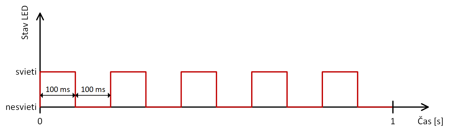
The following examples demonstrate various methods of blinking an LED using a timer. The LED should blink 5 times per second, with the LED on-time being equal to the LED off-time. The timing diagram below corresponds to this scenario.
Example 1
This example demonstrates the simplest method of generating a time delay using Timer0 in its default Normal mode by polling the overflow flag.
The timer is started by configuring a prescaler of 8 in the TCCR0B register. With an 8 MHz MCU clock, the TCNT0 register increments at a frequency of 1 MHz (every 1 µs). An overflow of the 8-bit counter (transition from 255 to 0) occurs every 256 µs, setting the overflow flag TOV0 in the TIFR0 register. The main loop polls this flag, clears it in software by writing a logic one, and increments an overflow counter. Once 391 overflows are accumulated (391 × 256 µs ≈ 100.1 ms), the state of pin PORTB0 is toggled, resulting in the LED blinking with a period of 200 ms (5 Hz frequency).
#include <avr/io.h>
int main(void)
{
DDRB=255; //PORTB ako vystupny (vsetky piny)
PORTB=0; //vsetky vystupy na log.0 -> vsetky LED zhasnute
TCCR0B|=(1<<CS01); // zapne casovac, predelicka 8 -> frekvencia casovaca 1 MHz
unsigned int pocet_preteceni=0; //pocitadlo preteceni
while (1)
{
if ((TIFR0&(1<<TOV0))==(1<<TOV0)) //ci nastalo pretecenie
{
pocet_preteceni++; //inkrementovanie poctu preteceni
TIFR0|=(1<<TOV0); //nulovanie priznaku pretecenia zapisom log.1
}
if (pocet_preteceni==391) //391 preteceni = 100.096 ms
{
pocet_preteceni=0; //aby sa odznova pocitali pretecenia
PORTB^=(1<<PORTB0); //zmena stavu LED na pine PORTB0
}
}
}
Example 2
In the second example, the time delay is implemented by directly reading and manually clearing the value stored in the timer data register TCNT0.
The timer Timer0 runs with a prescaler of 8, which increments the counter every 1 µs at an 8 MHz MCU clock. The main loop continuously checks the current count in TCNT0. When the value reaches or exceeds 200 (corresponding to 200 µs), the register is reset to zero in software and an auxiliary cycle counter is incremented. After 500 iterations (500 × 200 µs = 100 ms), the pin PORTB0 is toggled, turning the LED on or off. While straightforward, manually resetting TCNT0 in code introduces slight timing jitter due to instruction execution overhead.
#include <avr/io.h>
int main(void)
{
DDRB=255; //PORTB ako vystupny (vsetky piny)
PORTB=0; //vsetky vystupy na log.0 -> vsetky LED zhasnute
TCCR0B|=(1<<CS01); // zapne casovac, predelicka 8 -> frekvencia casovaca 1 MHz
unsigned int pocitadlo=0;
while (1)
{
if (TCNT0>=200) //ci ubehlo 200us
{
pocitadlo++; //inkrementacia pocitadla (kazdych 200us)
TCNT0=0; //nulovanie casovaca, aby znova pocital od nuly
}
if (pocitadlo==500) //ci ubehlo 100ms=500 x 200us
{
pocitadlo=0;
PORTB^=(1<<PORTB0); //bitova negacia
}
}
}
Example 3
In the third example, the time delay is generated using the hardware Output Compare Match mechanism in the default Normal mode of Timer0.
The output compare register OCR0A is loaded with a value of 200. With the prescaler configured to 8 and an MCU clock of 8 MHz, the counter register TCNT0 increments every 1 µs, triggering a compare match event every 200 µs. This event asserts the compare flag OCF0A in the TIFR0 register. The main execution loop polls this flag, clears it in software by writing a logic one, and increments an auxiliary loop counter. Once 500 match events are accumulated (500 × 200 µs = 100 ms), the state of pin PORTB0 is toggled, reversing the LED state. This method provides better timing stability than direct polling of the TCNT0 register because the compare condition is detected purely by dedicated timer hardware.
#include <avr/io.h>
int main(void)
{
DDRB=255; //PORTB ako vystupny (vsetky piny)
PORTB=0; //vsetky vystupy na log.0 -> vsetky LED zhasnute
TCCR0B|=(1<<CS01); // zapne casovac, predelicka 8 -> frekvencia casovaca 1 MHz
OCR0A=200; //nastavenie registra zhody (200 = 200us)
unsigned int pocitadlo=0;
while (1)
{
//ci bit OCF0A v reg. TIFR0 je nastaveny na jednotku ->
//doslo k zhode TCNT0 a OCR0A
if ((TIFR0&(1<<OCF0A))==(1<<OCF0A))
{
pocitadlo++;
TIFR0|=(1<<OCF0A); //zmazanie priznaku zhody zapisom log.1
}
if (pocitadlo==500) //ubehlo 100ms=500x200us
{
pocitadlo=0;
PORTB^=(1<<PORTB0); //zmena stavu LED na pine PORTB0
}
}
}
Example 4
The fourth example demonstrates the most efficient and standard design pattern for embedded timers: combining the hardware CTC (Clear Timer on Compare Match) mode with an interrupt service routine (ISR).
Setting the WGM01 bit in the TCCR0A register activates CTC mode, causing the timer counter TCNT0 to be automatically reset to zero by hardware the instant it matches the threshold in OCR0A (value 200 = 200 µs). By asserting the OCIE0A bit in TIMSK0 and calling the sei() macro, the Output Compare Match A interrupt is enabled. Every 200 µs, the MCU automatically branches to the TIMER0_COMPA_vect interrupt routine to increment the counter. After 500 iterations (100 ms), pin PORTB0 is toggled. The key advantage of this architecture is that timing management requires zero CPU polling in the foreground—the while(1) loop in main() remains free for other application tasks or low-power sleep modes.
#include <avr/io.h>
#include <avr/interrupt.h> //kniznica preruseni
unsigned int pocitadlo=0;
ISR(TIMER0_COMPA_vect) //obsluha prerusenia casovaca0
{
//sem hlavny program (main) "odskoci" kazdych 200us
pocitadlo++;
if (pocitadlo==500) //ubehlo 100ms = 500 x 200us
{
pocitadlo=0;
PORTB^=(1<<PORTB0); //zmena stavu LED na pine PORTB0
}
}
int main(void)
{
DDRB=255; //PORTB ako vystupny (vsetky piny)
PORTB=0; //vsetky vystupy na log.0 -> vsetky LED zhasnute
TCCR0B|=(1<<CS01); // zapne casovac, predelicka 8 -> frekvencia casovaca 1 MHz
OCR0A=200; //nastavenie registra zhody (200 = 200us)
//automaticke nulovanie TCNT0 pri dosiahnuti hodnoty v OCR0A
TCCR0A|=(1<<WGM01);
TIMSK0=(1<<OCIE0A); //zapnutie prerusenia casovaca0
sei(); //globalne povolenie preruseni
while (1)
{
}
}